Convert a Cisco 2600 Series Access-Point from Lightweight to Autonomous and back again!
The Cisco 2600 series Access-point is a controller based AP, which means by default the AP is shipped with “AP3G2-k9w8” version of the IOS. At boot the device will try and locate a controller and try to associate itself with it. There are several methods it uses to do this which is quite clever, these are the following:
Broadcast: The AP will send out a broadcast looking for the WLC, if on the same subnet the WLC will respond, they will both exchange certificates using a capwap tunnel. the capwap tunnel is built using DTLS – Datagram Transport layer Security – “encryption” on top of UDP traffic.
DHCP: the AP will look for option 43 which can be configured on any DHCP server for the IP address of the WLC, they will both communicate using capwap.
DNS: the AP will perform a DNS lookup for “CISCO-CAPWAP-CONTROLLER” to resolve the IP address of the WLC and begin communication using capwap.
Failing the above the AP will keep trying again and again, reboot and keep looping……
At this moment we might realise we have purchased the wrong type of AP as we have no controller to manage this AP and our wireless network is a for a small deployment? Not to worry as Cisco have though of this….. we can “Convert” a lightweight (Controller based) access-point to a autonomous (Standalone) access-point and back to lightweight again.
There are several ways of converting the AP, the two most common are:
- Pressing the “Mode” button on the device to transfer the image into the AP using an TFTP Server, this requires the re-naming of the image to a filename the AP will look for upon boot. Normally for this method to work you would plug the AP directly into the laptop’s Ethernet port and configure networking. Quick and easy if you have a power adapter for the AP.
- Manually TFTP across the image and force the access-point to use it. This is the most successful way of converting the AP if you do not have a power adapter and need to use a POE switch.
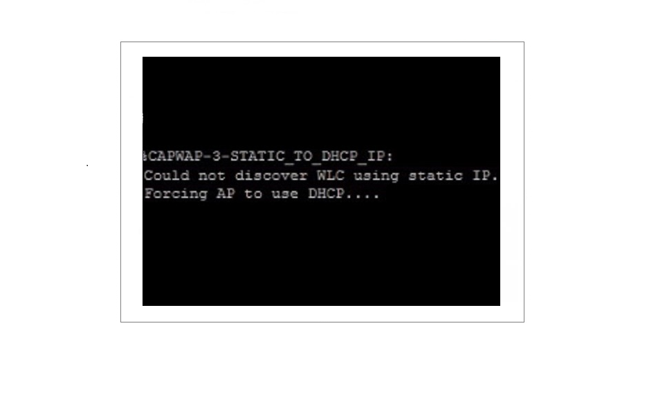
In this step-by-step guide we will use a 2600 Series AP, a TFTP Server, a DHCP Server and a POE switch (for the AP) all configured in one subnet. We will perform the conversion using the second option to manually TFTP the image across, once the AP is successfully converted we will then revert the AP back to lightweight. I must advise that using a DHCP server to lease out an IP to the AP is essential for LAP to AAP type of conversion, otherwise the AP will forcefully change a statically assigned IP to DHCP and break the communication during the extraction process. Lets get started!
Obtain the correct Autonomous IOS image
![]()
1. Download the above named IOS image from Cisco, and place it into the root folder of your TFTP server. This image is only for converting the 2600 series AP from Lightweight to Autonomous . Lightweight images will always have a “w8” in the filename and Autonomous Images will have a “w7”
![]()
Configure theTFTP Server
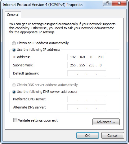
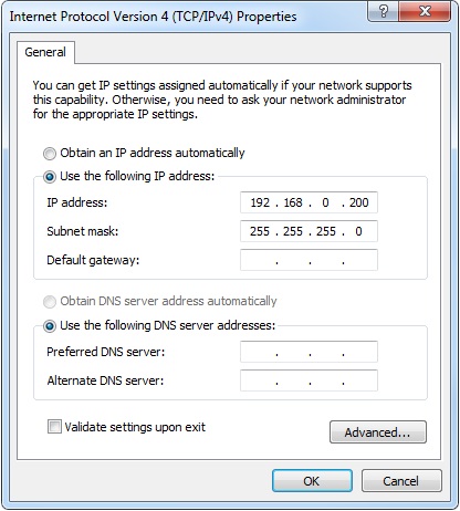
1. Configure the TFTP server to use a valid IP address on your subnet in this case I have used the following:
IP address: 192.168.0.200
Subnet mask: 255.255.255.0
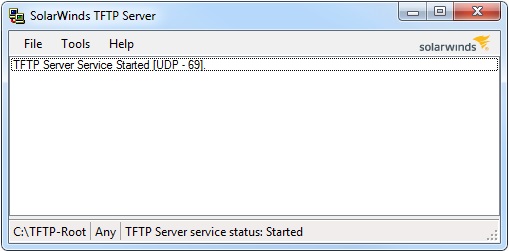
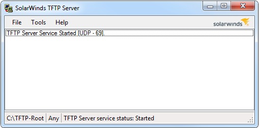
2. Run the TFTP server application
Convert the Access-Point to Autonomous
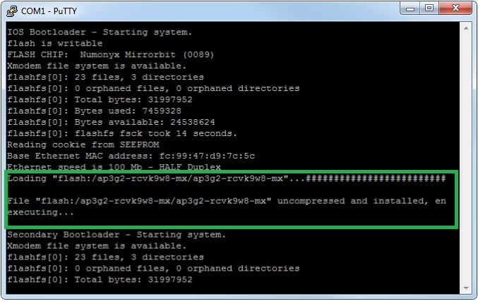
1. Connect to the AP using a console cable and Putty, plug in the Ethernet cable from the POE switch into the AP and wait for the device to boot. During bootstrap we can see the name of the IOS image that is being loaded – “ap3g2-rcvk9w8-mx”
2. At the login prompt, login to the device using the default username/password
Username: Cisco
Password: Cisco
Enable Secret: Cisco
Check what IP address the device has picked through DHCP by entering the following:
#debug capwap console cli – This command is used to enter the CLI troubleshooting mode, without this command the AP will not recognise the standard IOS cmds
# ip interface brief – Displays a list of interfaces and IP addresses
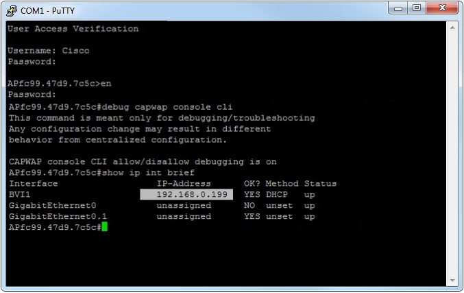
From the output we can see that DHCP has issued the device 192.168.0.199. Now we need verify connectivity between the AP and the TFTP server to make sure they can reach each other.
From the AP ping the TFTP server- #ping 192.168.0.200

From the TFTP server ping the AP- #ping 192.168.0.199
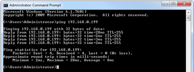
3. Specify the location of the image for extraction on the TFTP server and force the AP to boot the new IOS. (this can take up to 5mins to complete)
#archive download-sw /force-reload /overwrite tftp://192.168.0.200/ap3g2-k9w7-tar.152-4.JA1.tar

The archive command extracts the new IOS and deletes the default one.
4. Once the device has completed extracting files, deleting the old IOS and rebooting, it will display an “AP>” prompt rather that the long AP host name previously displayed. At this prompt enter the following:
#enable
#password Cisco
#show version
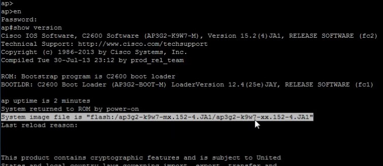
Confirm the new w7 IOS is now in use, then type:
#show ip interface brief – This will allow us to verify the current DHCP adddress obtained by the device, it should be the same as before but its a good idea to verify.

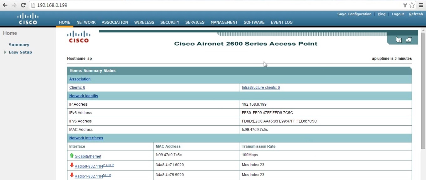
5. Open a web browser and navigate to the IP address of the AP – “192.168.0.199” an authentication prompt will be displayed. Login to the device using the default username/password – Cisco/Cisco

Once authenticated the web GUI will be displayed for the Autonomous Access-Point – from here you can begin configuring the AP and set-up the wireless network, you can fully manage the AP either from the CLI or the web GUI.
Revert the AP back to Lightweight
After using the wireless access-point in autonomous mode for a while you may find that your requirements have grown and you now have the need to deploy multiple APs along with a Wireless LAN Controller to manage those APs. As the 2600 series AP is a controller based AP we can simply revert it back to work with a WLC. In this process we reset the AP back to factory default and statically configure the BVI1 interface with an IP, this will only be for the conversion process as once the AP is converted and if no controller is found it will forcefully change the interface mode of BVI1 into DHCP this happens automatically. The topology will remain the same – 2600 Series AP, a TFTP Server, a DHCP Server and a POE switch.
Obtain the correct Lightweight IOS image
![]()
1. Download the above named IOS image from Cisco, and place it into the root folder of your TFTP server. This image is only for converting the 2600 series AP from Autonomous to Lightweight. This image is also known as a recovery image as this is not the final image the AP would use once its associated with a WLC. Normally at WLC discovery and association process the AP downloads a new image from the controller.
![]()
Configure the TFTP Server
1. Configure the TFTP server to use the a valid IP address on your subnet, in this case I have used the following.
IP address: 192.168.0.200
Subnet mask: 255.255.255.0
2. Run the TFTP server application
Reset, Configure and Convert the Access-Point to Lightweight
1. Connect to the AP using a console cable and Putty, plug in the Ethernet cable from the POE switch in to the AP and wait for the device to boot. At the prompt of your host name – type “Enable” and login in.
Erase the start-up config and reset the AP back to factory default, by entering the following:
#erase startup-config
#reload
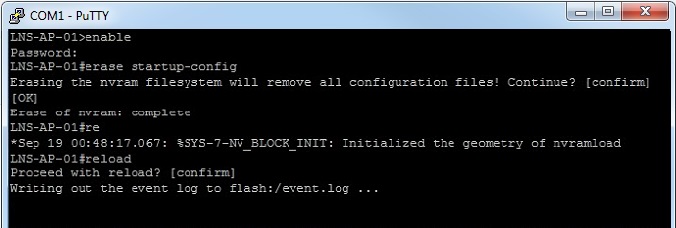
2. The reload cmd will reboot the AP , once the device is back up, login and Configure the BVI1 interface with an IP address and subnet mask
#conf t
#int bvi1
#ip address 192.168.0.199 255.255.255.0
#no shut

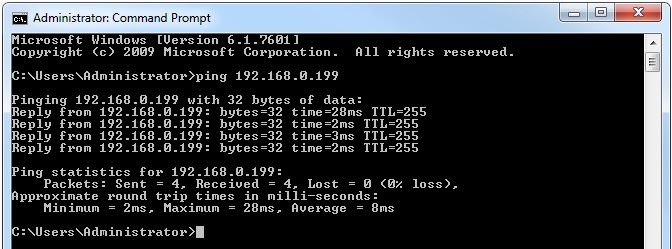
3. From the AP ping the TFTP server- to verify connectivity.
#ping 192.168.0.200

From the TFTP server ping the AP
#ping 192.168.0.199
4. Specify the location of the image for extraction on the TFTP server and force the AP to boot the new IOS. (this can take up to 5mins to complete)
#archive download-sw /force-reload /overwrite tftp://10.0.0.3/ap3g2-rcvk9w8-tar.152-4.JA1.tar
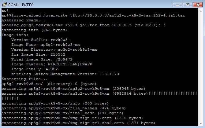
The archive command extracts the new IOS and deletes the previous one.
5. Once the device has completed extracting files, deleting the old IOS and rebooting, we can see the w8 IOS is being loaded…
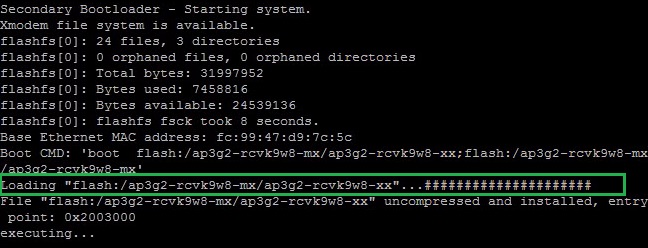
WLC discovery and join process
The AP will display a “APfc9947d97c5c>” rather that the “AP” prompt displayed previously, this hostname is usually the MAC address of the device. The device will now start looking for a WLC by using the methods mentioned earlier.
from the output below, we can see that :
- The AP has failed to locate the WLC by performing a DNS lookup – this is because we dont have a DNS server configured.
- the AP has failed to locate the WLC using DHCP – we didnt setup DHCP with option 43
- the AP has successfully sent out a broadcast and located the WLC, it then sent out a DTLS request to establish a capwap tunnel and started downloading an image from the controller.
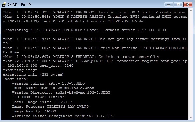
Once the image is updated, the AP will reboot, during the boot process the AP and WLC will re-connect once again.

Finally the access point will be visible in the WLC web GUI and available for central management.


