Deploy a Cisco Virtual Wireless LAN Controller and Complete Initial Setup
In this step by step guide I will show you how to deploy a Virtual Wireless LAN Controller and complete the initial setup process.
Deploy the Cisco vWLC OVF Template
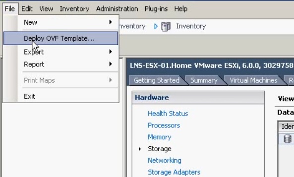
1. Download the vWLC OVF template from the Cisco website and save it in a suitable place, you can download a trial version valid for up to 60 days. Launch vSphere and select “File” and click “Deploy OVF Template”
2. Browse for the OVF template file and click “Next”

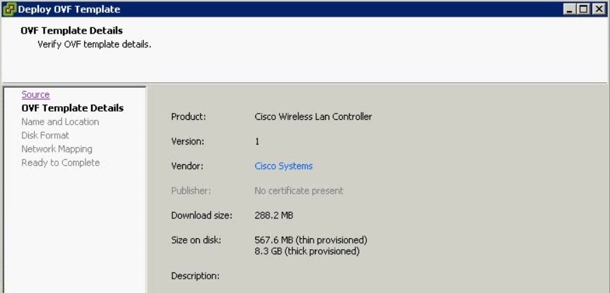
3. At the Summary window verify the details of the VM and hit “Next”
4. Give the Appliance a name and click “Next”

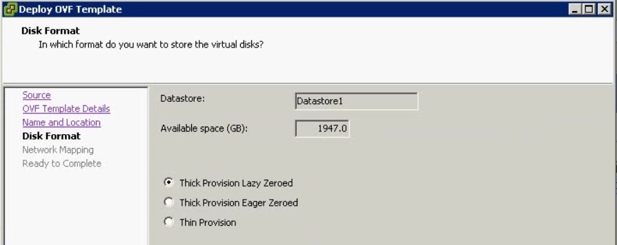
5. Select “Thick Provision Lazy Zeroed” and click “Next”
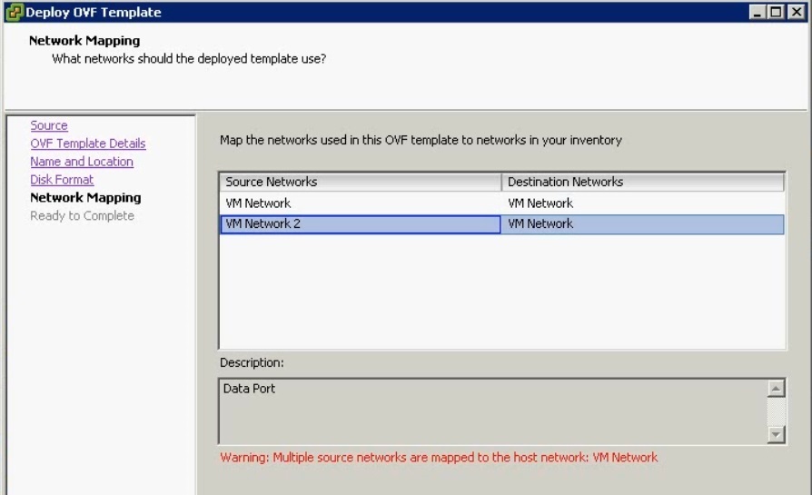
6. At the network mapping screen click “Next”
7. At the Summary screen verify all the details are correct, make sure “Power on after deployment” is unticked and hit “Finish”
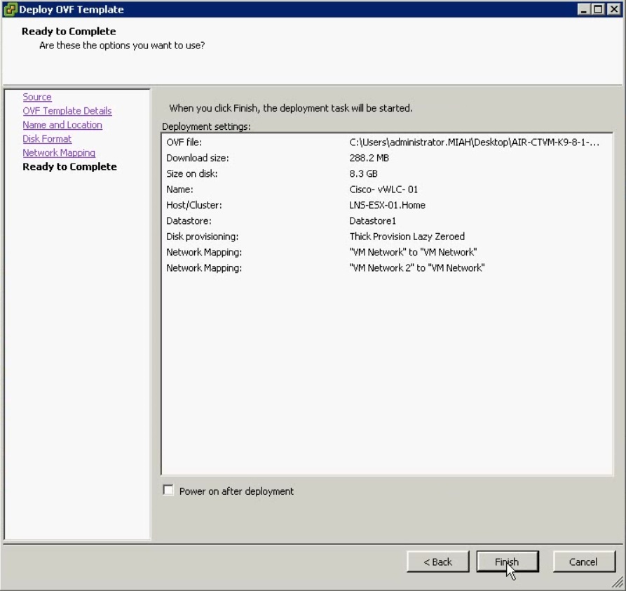
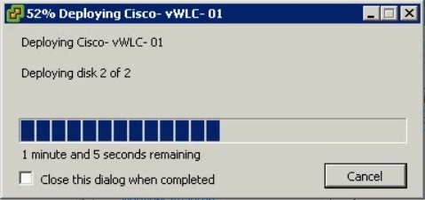
The template will begin to deploy, this can take a few minutes to complete, once completed successfully hit “Close”

Edit the Virtual Appliance
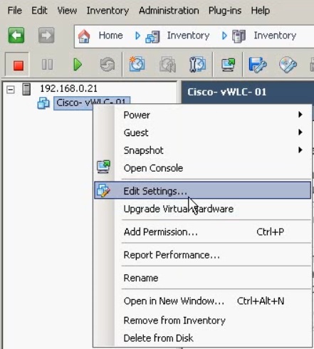
1. Right click the VM and select “Edit Settings”
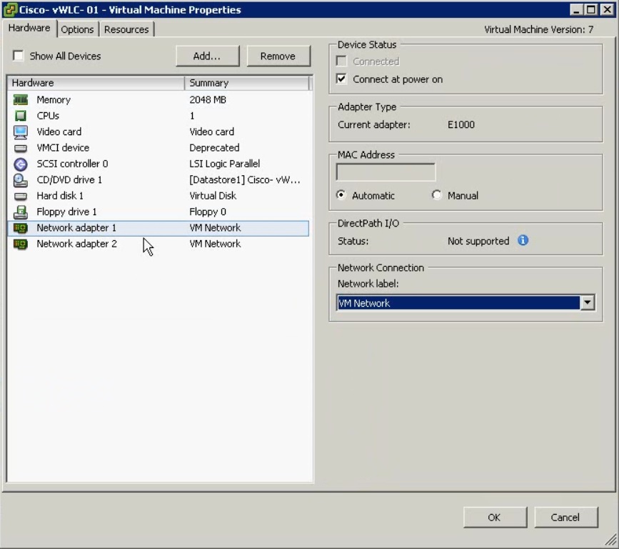
From the Virtual Machine properties make sure “Network Adapter 1” is connected to the management VLAN as this port will be used for the service interface on the vWLC.
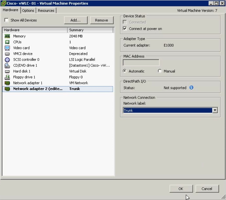
Next make sure “Network Adapter 2” is connected to a Trunk interface, this will be used by the vWLC as the management interface to communicate with the Access-points via CAPWAP. Click “OK”
Begin Initial Setup
1. launch a console window and Power on the virtual machine, Hit enter for the device to begin the boot process.
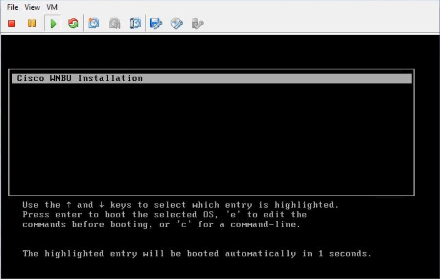
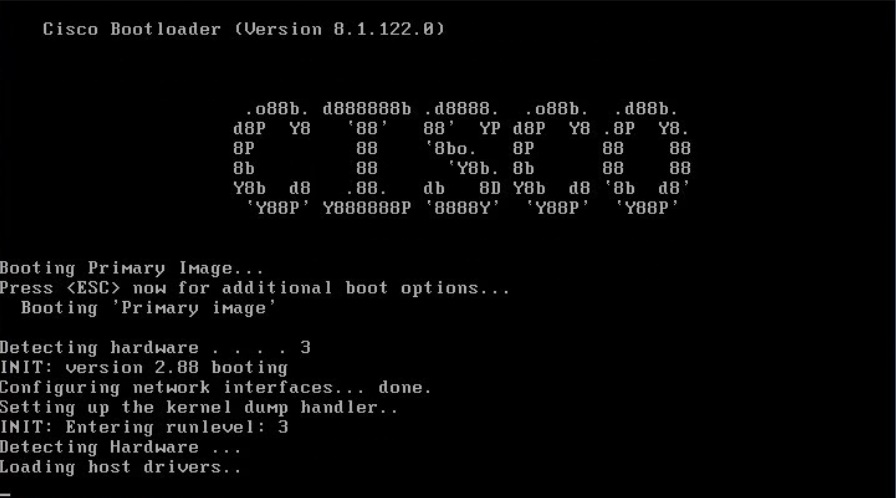
2. At the prompt “Would you like to terminate autoinstall” type “Yes”

The device will now walk us through a set of configuration commands which allows us to define the settings we want for the controller.
3. Create a Administrative account which will be stored locally on the device, at the prompt give the account a name and password.

4. Type “Static” to set the service interface IP address and netmask manually, this interface will be used for “Out of Band” management and should be on a management VLAN

5. Enter the Management IP address, netmask, & Default gateway information – this cannot be on the same subnet as the service interface! Enter the VLAN (If any) information, 0 can be used if the controller doesn’t belong to any VLANs. By default the Interface port number will be 1, finally enter the address of a DHCP server that will serve the scopes of the Wireless Access-points.

6. At the prompt for the IP address of a “Virtual Gateway” simply enter 1.1.1.1, this would only be used in an environment where three or four WLC’s are deployed for the purpose of “Roaming” where users can go between any access points and between different controllers, all of the controllers in the same mobility group would use the same VIP.
![]()
7. Give the controller a mobility group name
![]()
8. Give your first SSID a name
![]()
9. At the prompt to configure DHCP Bridging type “No” this can always be setup at a later stage.
![]()
10. Select “Yes” to allow the use of static IP addresses
![]()
11. You have the option to configure a RADIUS server at this stage, however in this example we will say “No” at the prompt.

12. Enter the country code “GB”
![]()
13. at the prompt to enable the radios select yes for all four

14. If you have a NTP server you may configure this here, alternatively you can manually enter the date/time information

15. if you are using IPv6 in your network you configure these options now alternatively type “No”
![]()
16. If the configuration is correct, type “Yes” and the VM will save the changes and reboot. if you have made mistakes or want to start again select “No”
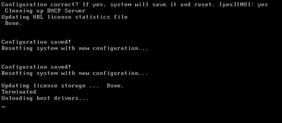
Once the VM has rebooted successfully, the console will display a “User” prompt. You can login using the credentials specified earlier to carry out further command line configuration, or we can also use the web GUI interface.

Access the GUI Web Interface
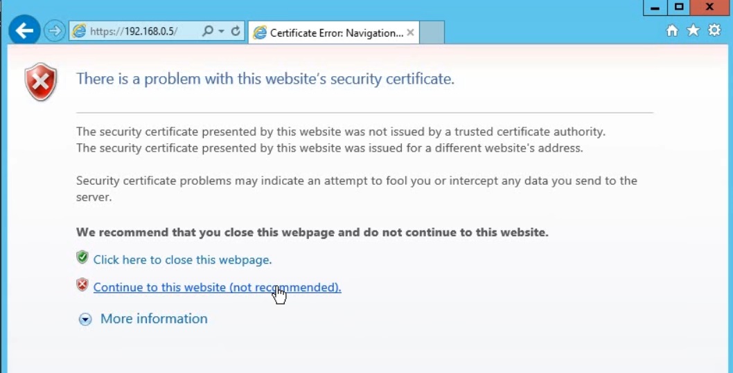
1. launch a web browser and enter the IP address of either the service interface or the management interface. At the certificate error click “Continue to this website (not recommended)” the error is displayed only because the device is using a self signed certificate and our browser doesn’t recognise it.
2. Click “Login” and insert the credentials created earlier.
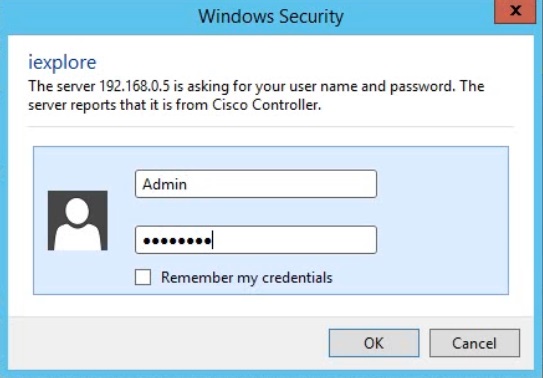
Once the user is authenticated, we will have access to the interface where we can begin configuring our Wireless LAN in more depth.
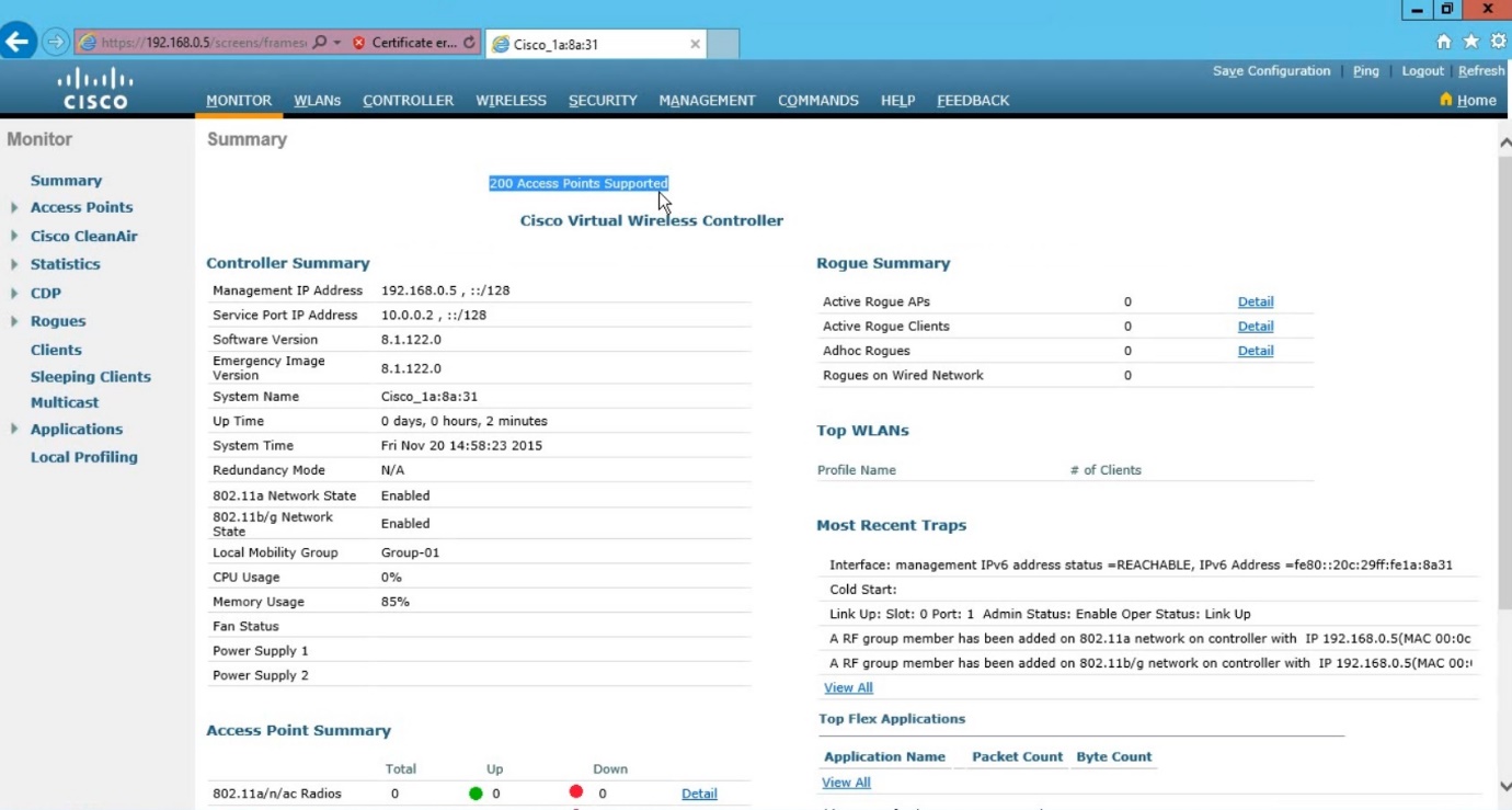
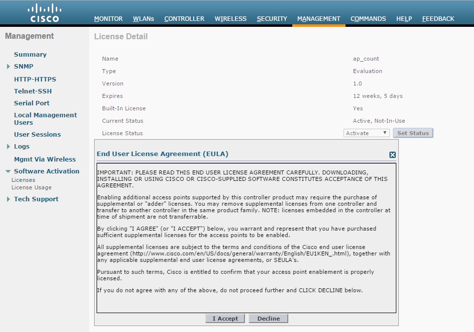
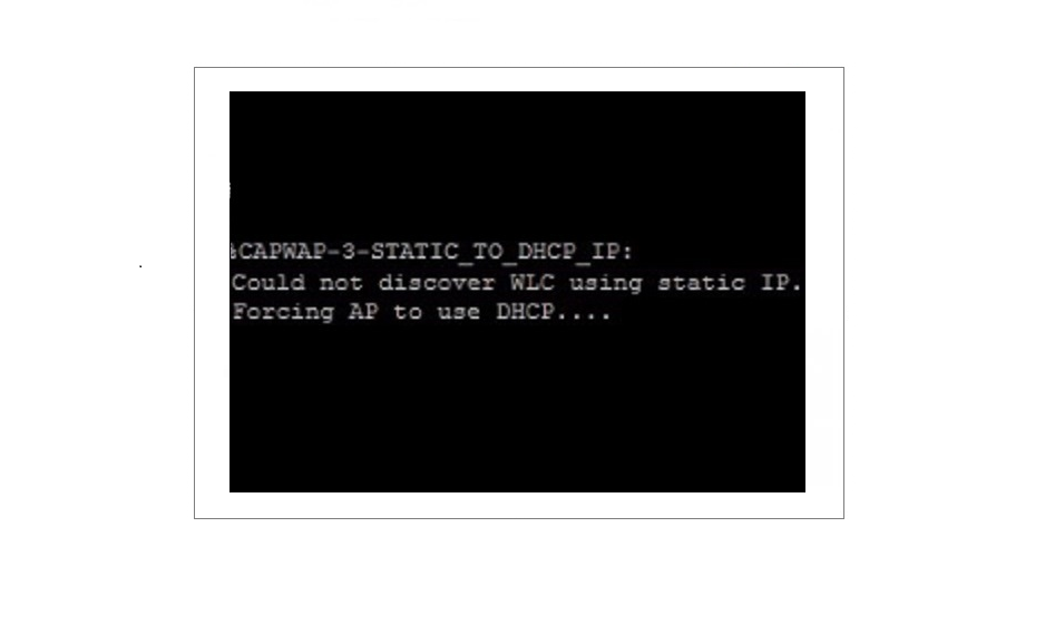
Before we can begin adding access-points to the controller, we must activate a valid licence – in this case we will activate the evaluation licence. If we don’t have a valid licence the APs will fail to establish a capwap tunnel to the controller, and therefore fail to associate. From the top menu navigate to “Management”-“Software Licence”-Licences” and click on the licence name “ap count”. click on the “Set Status” button for the licence agreement and click accept. finally save the configuration and reboot the WLC.
