Cisco Wireless – Setting up FlexConnect aka “H-REAP” with Local Switching of Multiple VLANs
FlexConnect also known previously as H-REAP – “Hybrid Remote Edge Access Point” is usually set-up for branch sites which are connected via a WAN link, FlexConnect access points have the ability to perform local switching and authentication, which means they can make layer 2 forwarding decisions without having to send them up to the WLC using CAPWAP. The benefits of this type of set-up is, in the event that the WAN link goes down – the AP will still be able to service new clients, maintain connections and perform local switching until the WAN link is available again.
To support local switching of multiple VLANs the FlexConnect access point should be connected to trunk interface on the switch, although it can be used on a access port, plugging into an access port will only allow DHCP to issues addresses to clients from the same VLAN as the AP.
In this step-by-step guide we will look at configuring “FlexConnect” for an access-point to locally switch multiple VLANs. We will set-up multiple VLANs and Muliple SSIDs, the AP will receive an IP address from our VLAN1 – Management VLAN and as our clients connect to the relevant SSIDs we will be able to associate them with the relevant VLANs. e.g clients associated with SSID “VLAN10” will get IP address from DHCP for “VLAN10”.
I will be using a vWLC, a L3 switch, DHCP Server and an 2600 Series AP, Lets get started!
Create DHCP Scopes for all the required VLANs
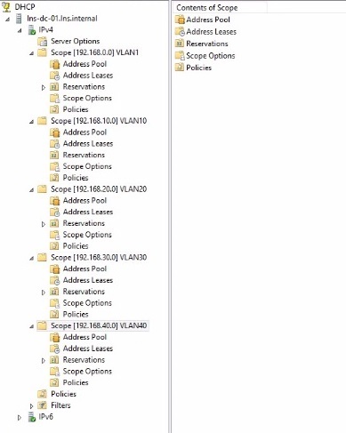
1. Create the scopes required in DHCP so that when wireless clients associate themselves with an SSID, DHCP will be able to lease out an address from the correct subnet. In this example I have used a Microsoft DHCP Server with the following:
VLAN1 – Native/Management VLAN – 192.168.0.0 /24
VLAN10 – 192.168.10.0 /24
VLAN20 – 192.168.20.0 /24
VLAN30 – 192.168.30.0 /24
VLAN40 – 192.168.40.0 /24
Configure the Switch
1. Configure the trunk interface for the Access Point on the switch, if this is set as an access port the associated clients will only receive IP addresses from that access port vlan.

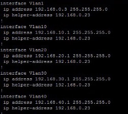
2. Optional Step – Configure the SVI interfaces on the switch if required, normally this would be done on the core switch at the main site for intervlan routing purposes, the interfaces would also point to a DHCP server using the IP Helper- Address.
Configure FlexConnect on the AP
1. Login to the Wireless LAN Controller, and click “Wireless” – “Access-Points” – “All APs” – “name of AP” to bring up the configuration details. From the “General” Tab click the drop-down box “AP Mode” and select “FlexConnect”

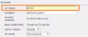
2. Give the AP a name and click on “Apply”
the Access-Point will reboot to complete the mode change, the WLC will display a warning, click “OK”

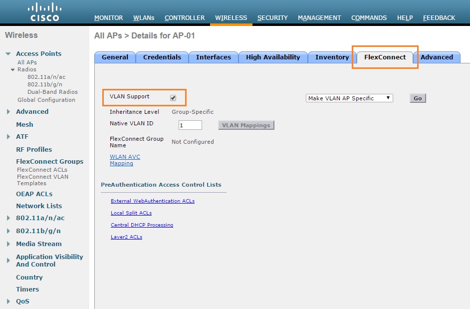
3. Once the AP is back up navigate to “Wireless” – “Access-Points” – “All APs” – “name of AP” and click on the newly listed “FlexConnect” tab. Tick the “VLAN Support” tickbox and hit “Apply”
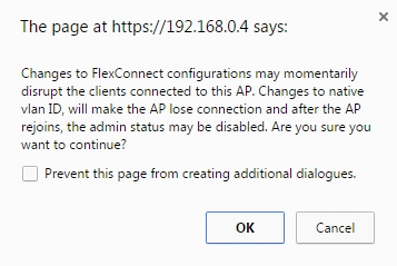
The WLC will display a warning regarding FlexConnect changes may disrupt clients, in our case we have no clients yet so its not a problem. Click “OK”
Create the Logical Interfaces
1. We now need to create the logical interfaces corresponding to each VLAN. Navigate to “Controller” – “Interfaces” – and click “New”, give the interface a name and enter the “VLAN Id” and click “Apply”
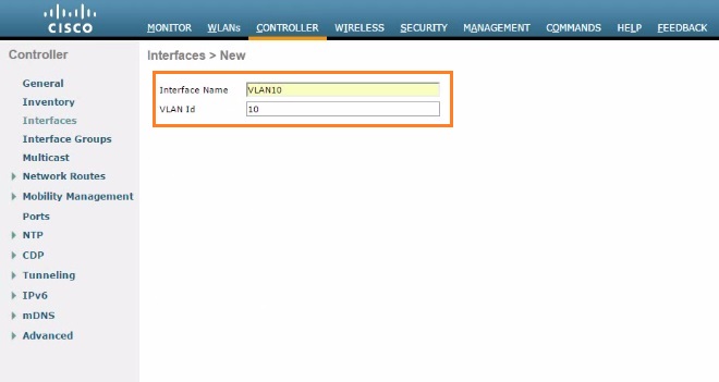
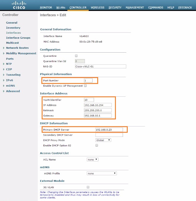
2. Input the interface details specific to the VLAN, in this step we are configuring the interface for VLAN10 which is in the 192.168.10.0 /24 subnet.
Insert the following for the interface and click “Apply”:
Port No – 1
VLAN Id – 10
IP address – 192.168.10.254
Netmask – 255.255.255.0
GW – 192.168.10.1
Primary DHCP Server – 192.168.0.23 (Microsoft DHCP Server)
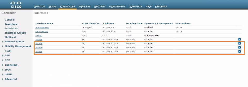
3. Once the Interface for the VLAN has been added, click “New” and repeat the above steps to continue adding the rest of the VLAN interfaces. from the below output we can see that VLAN10 is present but I have also added the interfaces for VLAN 20,30 & 40.
Create the WLANs (SSIDs)
1. Now that we have our logical interfaces setup we can create our WLANs and map the VLAN interfaces to them. Navigate to “WLANs” – “Create New”

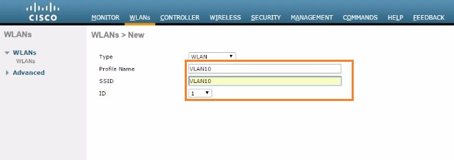
2. Give the WLAN a “Profile Name” and an “SSID” and click “Apply” this does not correspond with anything, the profile name and SSID can be anything you like. In this example to keep things uniform I have given them their VLAN names, meaning when clients connect to the SSID “VLAN10” they will be on “VLAN10”
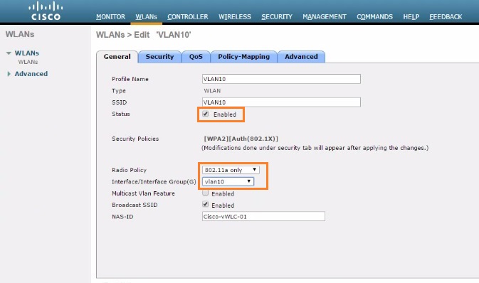
3. Specify the details of the WLAN, on the “General” tab tick the “Status” box to enable the WLAN, under “Radio Policy” select the policy you want to use – In this case ill be using “802.11a only” which will allow me to broadcast on the 5GHz range. Finally select the “Interface/Interface Group” of the logical interface created earlier.
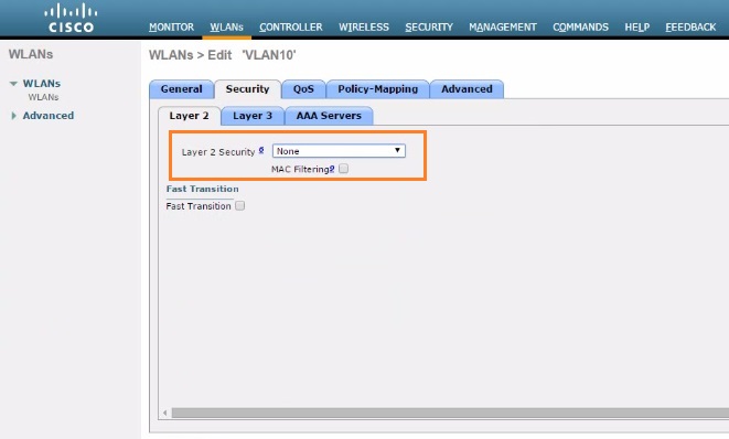
4. Select the “Security” tab and from the dropdown box select “None” – in this example I will not be using any authentication just to keep things simple, however in a production environment you must always use some form of authentication.
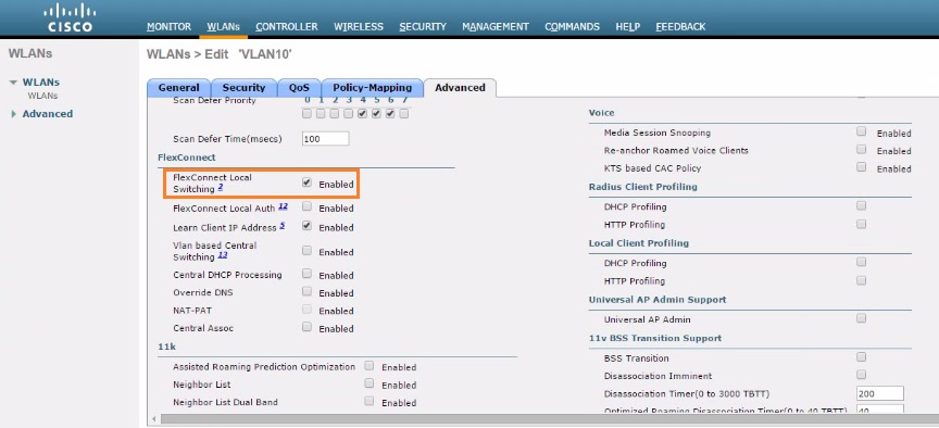
5. Click the “Advanced” tab and scroll down, under “FlexConnect” tick the box “FlexConnect Local Switching”, this will allow the WLAN to perform local switching.
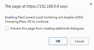
The WLC will display a warning – that mDNS snooping will be disabled if we use FlexConnect, this fine as we are not using any discovery services. Click “OK”
6. Once the WLAN has been created, select “Create New” and repeat the above steps for the remaining VLANs 20,30,40.

From the output below we can see that the WLANs for VLAN 10, 20, 30 and 40 have now been added.

Assign a Native VLAN Id & Check the VLAN Mappings
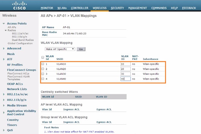
1. Navigate to “Wireless” – “Access-Points” – “All APs” – “name of AP” and click on the “FlexConnect” tab. Under “Native VLAN ID” insert the VLAN of your native VLAN which is routable back to the WLC, in this case the AP will be able to reach our WLC through VLAN1 as this is where we have configured our management interface, also the AP will obtain an IP address through DHCP on this VLAN. Hit “Apply” and click “VLAN Mappings”
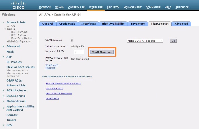
Verify the WLAN and VLAN Mappings are correct. Under inheritance they all should specify “Wlan Specific” meaning the VLAN mapping policy is being inherited from our WLAN policies which we created earlier.
Client Testing
Using a client device perform the following tests:
1. Check to make sure the SSIDs are visible
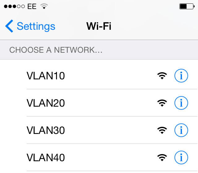
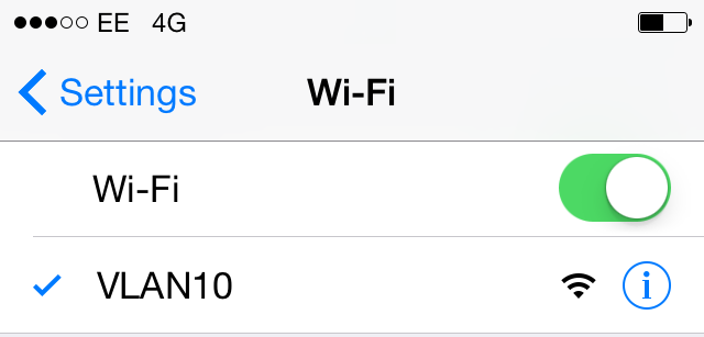
2. Make sure you can connect to each of the SSIDs, in this case VLAN10,20,30, & 40.
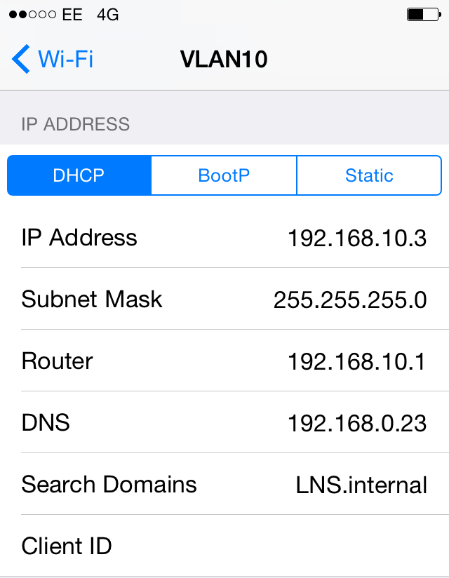
3. Verify the correct IP addresses are being obtained by the client when connected to the relevant VLAN.
4. Ping the Default Gateway & an IP on another subnet to verify connectivity/Intervlan routing.
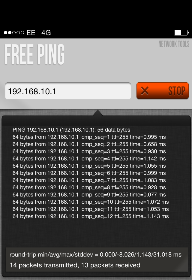
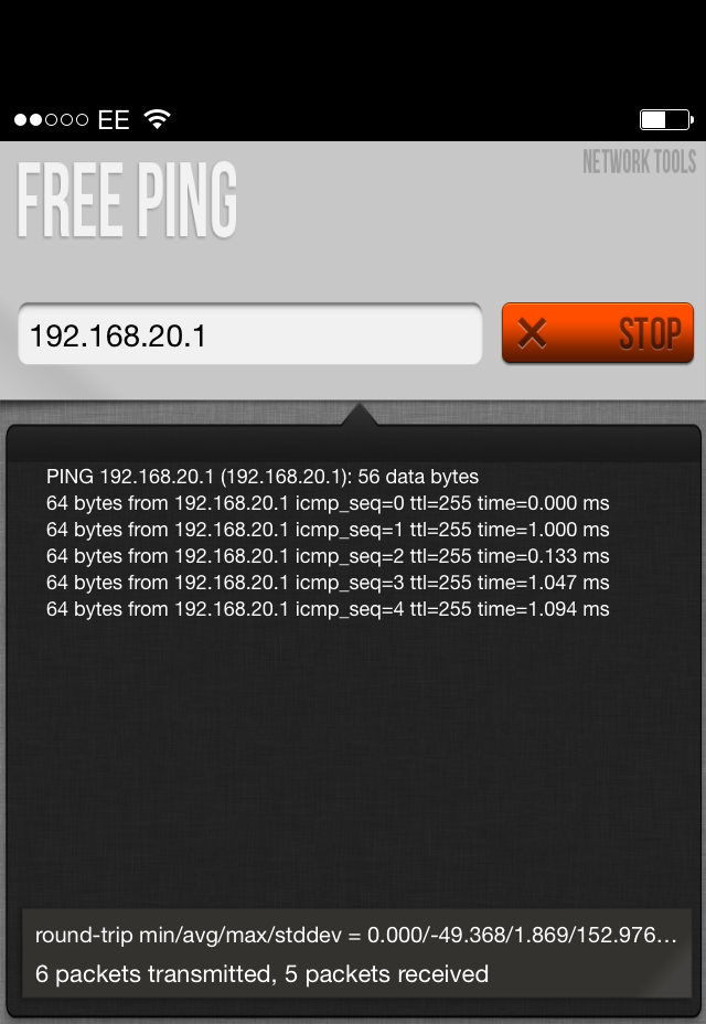
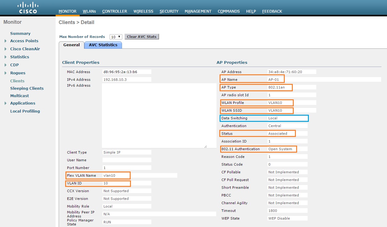
5. Finally On the WLC, Verify the connected client is visible and that local switching is being performed by the AP. Navigate to “Monitor” – “Clients”

Click on the “Client MAC Addr” and view the details of the client
