BPDU Filter and its Potential to Cause a Network Loop
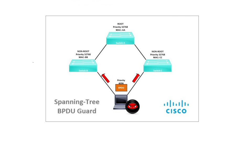
BPDU Guard, BPDU Filter, Root Guard and Loop Guard are all considered spanning tree security features, they all have different characteristics as to what they protect and how they work. Spanning tree attacks can harm the data-plane at Layer 2 therefore using spanning tree security we can mitigate “Man in the Middle” type attacks, protect against changes in the spanning tree topology, protect the “Root Bridge” and prevent overall network loops.
Spanning-tree “BPDU Filter” works similar to “BPDU Guard”, as it allows you to block BPDU’s. The major difference is that “BPDU Guard” will place an interface that receives the BPDU into an “err-disabled” state pretty much protecting the violating port while “BPDU Filter” just “filters” it leaving the port to stay up. If a user connects a switch on these ports, potentially this will cause a network loop. You must be careful if you are using BPDU filter and this should only be configured on interfaces in “Access Mode” which connect back to a “Host” device. This should never be configured on interfaces that connect to other switches.
BPDU Filter can be configured globally or on a port by port basis, and there is a difference between the two
Global – If BPDU filter is enabled globally, then any interface with “Portfast” configured will not send or receive any BPDU’s. However, when the port does receive a BPDU then it will lose its “Portfast” status, disable BPDU Filtering and act as a normal port.
Port by Port – If BPDU Filter is enabled on a port by port basis, the port will ignore incoming BPDU’s and it will also not send out any BPDU’s. This is the same as disabling spanning tree.
Network Loop example
Warning: do not carry out anything outlined in this guide on a live network, and always ensure you have the relevant permissions if you are testing this out for yourself, this should only be done in a lab environment or test network. This document is for the purpose of understanding how the technology works.
In the example below we will configure “BPDU Filter” on the switch interfaces individually, then we will connect these ports back to switches. The example will demonstrate a broadcast storm and how the technology is capable of taking down a network if it is used incorrectly. The below has been setup in GNS3, however the same applies to physical kit. Basic network connectivity has been configured and RSTP is blocking “E0/1” on “SW-2”

Lets Begin…
Step 1: lets take a look at the Spanning-tree topology as it looks before we enable BPDU Filter
SW-1
show spanning-treeFrom the output below we can see that the switch is running RSTP, “SW-1” is the root bridge and all the ports on the root are forwarding.

SW-2
show spanning-treeOn “SW-2” we can see that it is also running RSTP, the MAC address of the root bridge is “aabb.cc00.0300” which is the MAC of “SW-1”. Interface “E0/0” is the root port and “E0/1” is being blocked to prevent the loop.

Step 2: Lets take a look at the CPU usage of both switches
SW-1
show process cpuWe can see that they utilization is very low, as we would expect to see.

SW-2
show process cpu“SW-2 CPU” utilization is also low

As these devices are running of a VM in GNS 3 let’s take a look at the CPU usage of the GNS3 VM.
We can that it is operating normally with a low utilization

Step 3: Configure BPDU Filter on both switch interfaces.
SW-1
conf t
int e0/1
switchport mode access
switchport access vlan 1
spanning-tree bpdufilter enable
spanning-tree portfast  (Not required to make BPDU Filter work)
SW-2
conf t
int e0/1
switchport mode access
switchport access vlan 1
spanning-tree bpdufilter enable
spanning-tree portfast (Not required to make BPDU Filter work)
Step 4: Lets take a look at the Spanning-tree topology,
SW-1
show spanning-treeAs “SW-1” was the root bridge initially, nothing has changed on this switch, all ports are still forwarding.

SW-2
show spanning-treeOn “SW-2” we can see that the Spanning-tree topology has changed, as we are no longer sending and receiving BPDU’s on “E0/1” the port has transitioned from a blocking state and into a forwarding state. This now means that the port is no longer blocking traffic and there is a loop between the switches. If a broadcast enters the network, it will keep going round and round without any end. On a production network this will mean a network death as thousands of broadcast frames keep looping continuously.

Step 5: Generate some broadcast on the network, from “SW-1” ping “SW-2”
ping 192.168.1.2The first response is lost due to ARP, which is the broadcast. The network is now going to keep looping this broadcast, and if enough broadcast enters the loop the switches will become unresponsive and experience a high CPU utilisation.

From “SW-2” generate more broadcast traffic
ping 192.168.1.1ping 192.168.10.1
Both “SW-1” and “SW-2” have become unresponsive, as they are not responding we can’t check the CPU utilization, my expectation is that they will be at 100%, if this was physical kit we might have been able to check.


Looking at the GNS3 VM the CPU has spiked to 100%

Also on physical kit, at this point the lights would flash continuously really fast.

Global Configuration Example
Step 1. Configure BPDU Filter globally
spanning-tree portfast bpdufilter default (GNS3 CMD – spanning-tree portfast edge bpdufilter default)
Step 2. Allow ports to participate in BPDU Filter
int e0/0
spanning-tree portfast

