DHCP Snooping Concept/Implementation
DHCP Snooping is a layer 2 security technology built into the IOS of a switch. The switch will drop DHCP Server messages in order to prevent unauthorized/rogue DHCP servers from offering IP addresses to DHCP clients. This is a very valuable security measure that can be used to help mitigate the network from attacks.
DHCP requests are processed as follows
D – Discover – Client sends a discover packet looking for available DHCP servers
O – Offer – Server sends an offer packet back to the client
R – Request – Client sends a request packet to the server
A – Ack – Server sends an acknowledgement back to the client

DHCP Snooping works by being enabled globally on the switch where all ports become untrusted, it is then enabled on the VLAN and then trusted ports are set to allow DHCP server messages. We can also take it a step further and configure additional parameters, like DHCP rate limit which can slow down a DHCP starvation attack.
Once enabled DHCP snooping says – if I see any DHCP “Offer” or “Ack” coming into any untrusted ports, I will drop the packet. However if I see any “Discover” or “Request” packets they will still be allowed.
If any type of DHCP packets come in on a trusted port they will be allowed, trusted ports will mostly be trunk ports that lead to the real DHCP server and also an access port that the DHCP server is connected to. Trusted ports don’t need to be all trunk ports, I have seen some situations where engineers set all their trunks to be trusted, this is something that needs to be identified during the design phase.
DHCP snooping stores all the mappings of the layer 2 and layer 3 addresses into a database which is by default stored in the switches flash, This table can be used to validate which IPs have been issued by the real DHCP Server, it can also be used to implement “Dynamic ARP” inspection which is used to mitigate “ARP related attacks” it is recommended by Cisco to store this database centrally to ensure security and preserve the disk space of the switch.
DHCP snooping should be enabled only on access layer switches that connect back to the user community, it is rarely required on the distribution or core layer unless user devices are connected back to these layers- if you are using a Cisco validated design or Cisco’s LAN campus design this should not be the case.
By using DHCP snooping we can mitigate a “Man in the Middle Attack” where a malicious user would use a rogue DHCP server to issue users on a network an IP address making themselves the default gateway and routing traffic for the users. The malicious user would then be able to capture all the traffic as it passes through them, and the users would not be aware. Port security should be used in conjunction with DHCP snooping to prevent a “DHCP Starvation Attack” this way the number of requests for IP addresses from the real DHCP server is not exhausted as part of a DOS attack before a malicious user uses a rouge DHCP server.
We can also mitigate an accidental network outage where a user plugs in a rogue DHCP server not realising the device is handing out IP addresses to users, these users would then potentially loose network connectivity to the LAN and WAN services.
Configuration example 1:
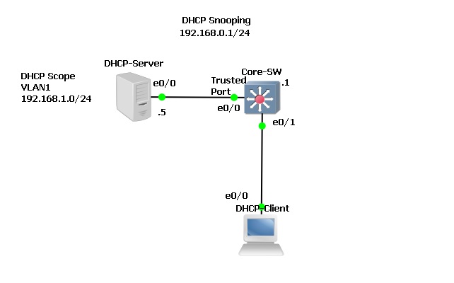
The topology below was setup using GNS3, all the devices are IOU devices that are acting as the roles specified. Currently DHCP is setup correctly for VLAN 1 the DHCP client is able to receive a valid IP from the server. In this setup we will use a single switch and single VLAN to show how DHCP snooping would block Server messages.
Complete LAB Config can be downloaded here –
DHCP-Server
Core-SW
Step 1. Let’s Validate DHCP is working
On the DHCP client we can see that there is a valid IP address on interface “Ethernet0/0” which is setup to receive it IP via DHCP.

On the DHCP server we can see that “192.168.1.9” has been issued to a client with the MAC listed in the DHCP binding table.

Step 2. Lets configure DHCP snooping on the “Core-SW”
#conf t – Enter global configuration mode
#ip dhcp snooping – enable DHCP snooping globally on the switch
#ip dhcp snooping vlan 1 – enable DHCP snooping for VLAN 1
#int e0/1 – Enter configuration mode for Ethernet 0/1 (DHCP client connected port)
#ip dhcp snooping limit rate 10 – Set a rate limit on DHCP packets per second to 10
#exit

Step 3. On the Client reset the network settings and verify that an IP is no longer available due to DHCP snooping, as we haven’t trusted the port that the DHCP server is connected to we shouldn’t see any IPs coming through to clients.

On the DHCP server we can see that there are no bindings as the server messages are not going through to the clients and the switch is dropping the packets.

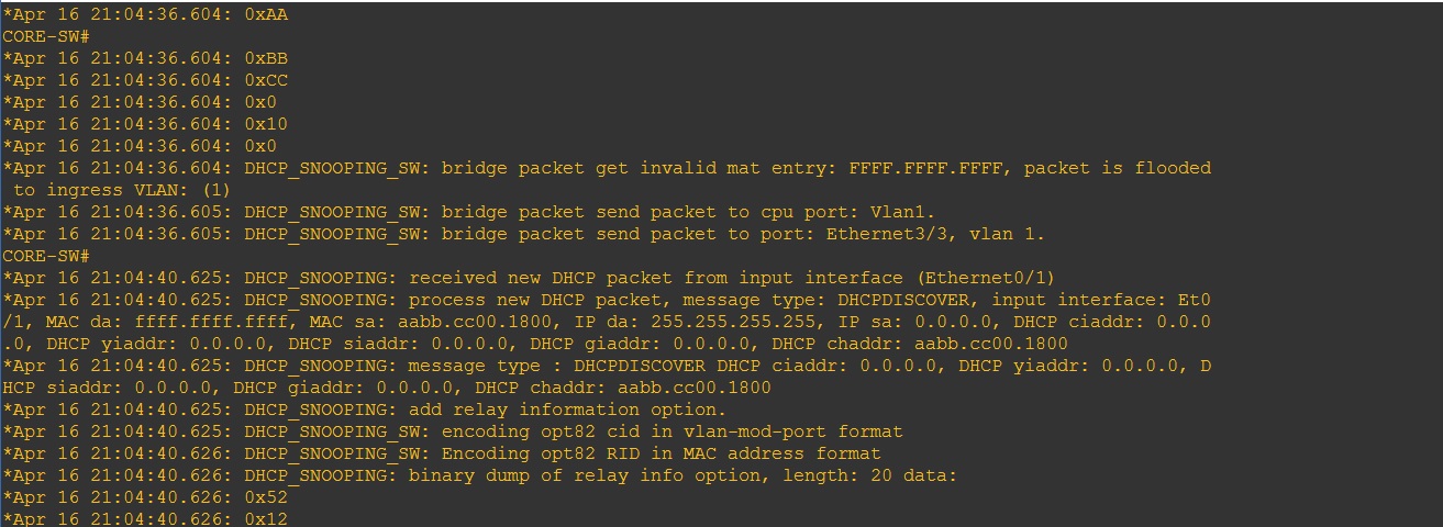
If we do a debug on the switch we can see what the switch is doing.
#debug ip dhcp snooping packet
From the output below we can see that the switch is receiving the “DHCPDISCOVER” packets and forwarding it on to “VLAN1” via a broadcast but we can’t see any Offer packets coming back into the switch.
Step 4. Let’s trust the port that is connected to the DHCP server so that the server messages can go through to the switch on this port.
#Conf t
#int e0/0
#ip dhcp snooping trust
![]()
Instantly after trusting the port that is connected to the DHCP server the client is able to obtain an IP address.

On the server we can see the DHCP binding for the IP address issued to the client.

On the switch we can see now see the “Discover” “Offer” “Request” and “Ack” messages going back and forth. 


Looking at the DHCP snooping binding table on the switch we can see the trusted and untrusted ports participating in DHCP snooping. All other ports on the switch will be un-trusted.
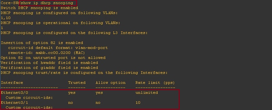
We can also check the DHCP snooping binding table to see what IP address is mapped to which MAC address. This is the table that can also be used for “Dynamic ARP inspection”.

Configuration Example 2:
In the Topology below we will look at a design that uses both a distribution and access layer, so something a little bit more real life. We will include a couple of VLANs to separate the DHCP server and user community, previously we used a flat VLAN so the DHCP server and client were on the same broadcast domain, in this example we will need to send the DHCP packets as unicast by configuring a “ip-helper address”. The blue circles are the ports that we will configure as trusted ports for DHCP snooping and the Access layer switches will all participate in DHCP snooping. We won’t run DHCP snooping on the switch labelled “CORE-01” as this will be our collapsed core.
Everything has been configured correctly and DHCP is already working let’s validate the configuration and take a look at how to implement DHCP snooping.
Complete LAB Configuration can be downloaded here –
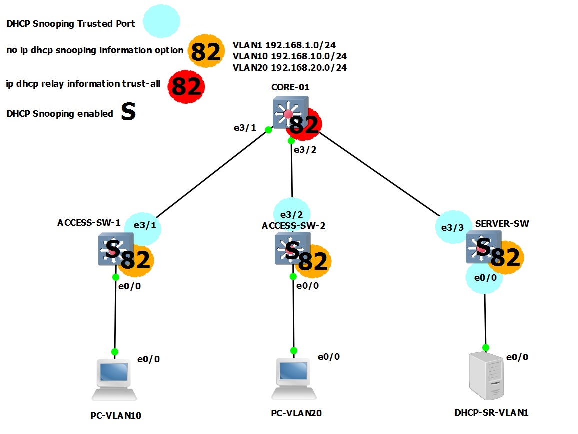
Step 1. Validation:
The two PC’s in VLAN 10 and VLAN 20 have valid IP addresses from their respective VLAN pool –
PC-VLAN10

PC-VLAN20

On the DHCP Server we can see the IP address that have been handed out

Step 2. Lets configure DHCP snooping on the “SERVER-SW”, this is where the DHCP server is connected on.
#conf t – Enter global configuration mode
#ip dhcp snooping – enable DHCP snooping globally on the switch
#ip dhcp snooping vlan 1 – enable DHCP snooping for VLAN 1 as this is the only VLAN coming off this switch. The DHCP server is on VLAN 1.
#exit

Step 3. Lets verify – the DHCP server is now not going to be able to send out any server messages as all the ports have become untrusted.
On the “SERVER-SW” we can see that “DHCPDISCOVER” messages are getting flooded.
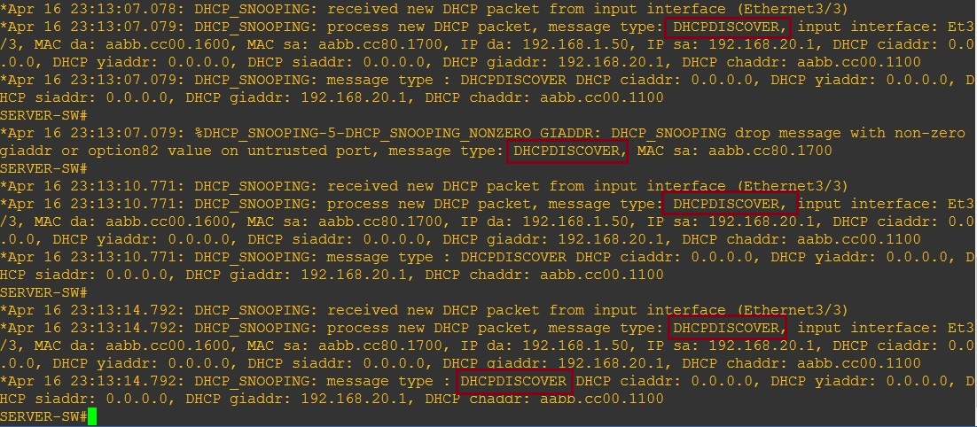
Clients in either VLAN are no longer able to receive an address

Step 4. Lets setup the trusted ports to allow the DHCP server messages through the “SERVER-SW”.
#conf t
#int e0/0 – DHCP Server
#ip dhcp snooping trust
#int e3/3 – Trunk towards “CORE-SW”
#Ip dhcp snooping trust
#exit

We can see on the DHCP server that the clients are now once again able to obtain IP addresses from the Server.

Lets take a look at the DHCP snooping configuration, we can see that DHCP snooping is enabled globally, and that DHCP snooping is enabled for “VLAN 1”. From the table we can see that “E0/0 and E3/3” are both listed as trusted ports. You may also notice “Insertion of option 82 is enabled” more on this further down.

Step 5. Although we have configured DHCP snooping on the “SERVER-SW” we still need to secure the “ACCESS-SW-1″ and “ACCESS-SW-2” and set the trusted ports.
ACCESS-SW-1
#conf t
#ip dhcp snooping
#ip dhcp snooping vlan 10,20
#int e3/1
#ip dhcp snooping trust
#exit

ACCESS-SW-2
#conf t
#ip dhcp snooping
#ip dhcp snooping vlan 10,20
#int e3/2
#ip dhcp snooping trust
#exit

Now that all three of the access switches have DHCP snooping enabled there seems to be an additional issue as the client devices can no longer obtain an IP address from the Server,
All three of the access switches are getting flooded with these messages indicating that the packets are being dropped.
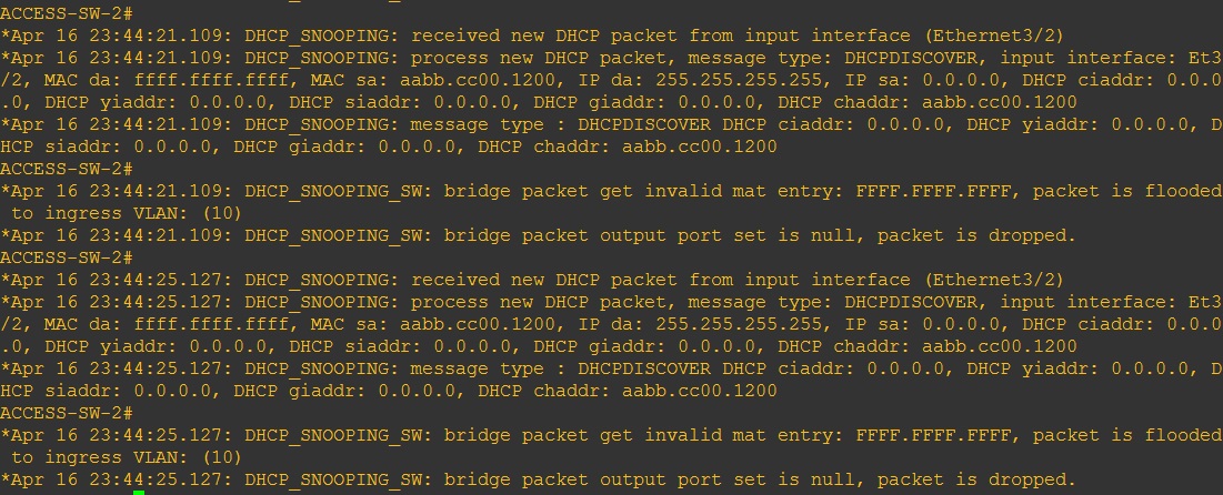
This to me is indicating a problem with “Option 82” which is enabled by default when DHCP snooping is being used,
The DHCP relay agent information (option 82) feature enables the DHCP relay agents (Catalyst switches) to include information about itself and the attached client when it forwards DHCP requests from a DHCP client to a DHCP server.
The DHCP server can use this information to assign IP addresses, perform access control, and set quality of service (QoS) and security policies (or other parameter-assignment policies) for each subscriber of a service-provider network.
When DHCP snooping is enabled on a switch, it automatically enables option 82.
If the DHCP server is not configured to handle the packets with option 82, it ceases to allocate the address to that request.
In order to resolve this issue, we need to disable the subscriber identification option (82) in the switches (relay agents) with the global configuration command, “no ip dhcp relay information option”.
Step 6. Let’s disable option 82 on all “ACCESS” switches.
SERVER-SW
#conf t
#no ip dhcp snooping information option

ACCESS-SW-1
#conf t
#no ip dhcp snooping information option

ACCESS-SW-2
#conf t
#no ip dhcp snooping information option

And on the “CORE-SW” we need to allow it to receive DHCP packets that contain relay information option with zero giaddr
CORE-SW
#conf t
#ip dhcp relay information trust-all

Step 7. Now let’s take a look at the clients – the clients are now able to obtain an IP address from the DHCP Server.


On the DHCP Server we can see the leased addresses in the DHCP binding table.

If we take a look at the DHCP snooping configuration on the “ACCESS-SW-1”, we can see that DHCP Snooping is enabled globally, DHCP Snooping is enabled for “VLAN 10,20”, Option 82 is “disabled” and the trusted port set is “E3/1”
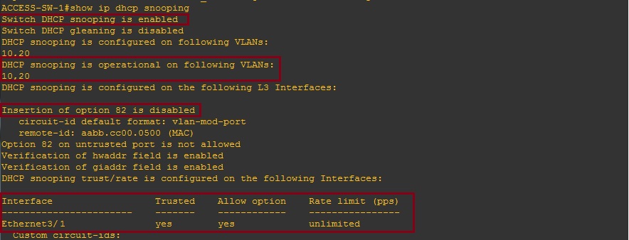
If we take a look at the binding table we can see the L2 and L3 mappings on the local DHCP snooping database.

On the DHCP Snooping configuration for “ACCESS-SW-2” we can see that DHCP Snooping is enabled globally, DHCP Snooping is also enabled for “VLAN 10,20”, option 82 is “disabled” and the trusted port is set to allow DHCP server messages is “E3/2”

Again if we take a look at the Snooping binding table we can see the mappings for “PC-VLAN20” 
