Deploying the ASAv using GNS3 and Integrating it with the Physical Network
GNS3 has been around for a while and is a fantastic tool to virtually create labs and test out Cisco technology, as it has evolved GNS3 has become better at providing support for many new devices. In older versions of GNS3 – running an ASA was very CPU intensive as the image used was initially something taken from a physical device, this caused multiple problems and the results always varied. Running multiple instance was also a problem unless the VM you were running GNS on, was a beast.
As Cisco released the virtual version of the ASA (ASAv) its compatibility became limitless and the GNS team were able to integrate the support of this device which works brilliantly.
Currently the ASAv is available to deploy using VMware ESXI, Hyper V and as a Qemu image.
In this step by step guide, we will deploy a Cisco ASAv in GNS3. We will walk through the process of getting it working correctly within the GNS3 environment. We will configure the device with basic management capability and install ASDM on a PC to be able to access and manage the device. We will then take it a step further and integrate it to the physical network.
The topology below has been setup using GNS3, the PC is a Windows VM running in VMware workstation – the VMnet(5) is assigned to the “192.168.5.0/24” network. Inside GNS3 the “Gig0/0” interface of the ASAv will be connected to a Cloud bridged to the same VMnet(5) so that they are on the same broadcast domain. The internet represents the physical network which then routes out to the real internet, this will also be bridged but to the logical adaptor of the GNS3 VM and then bridged again to the physical adaptor of the host.
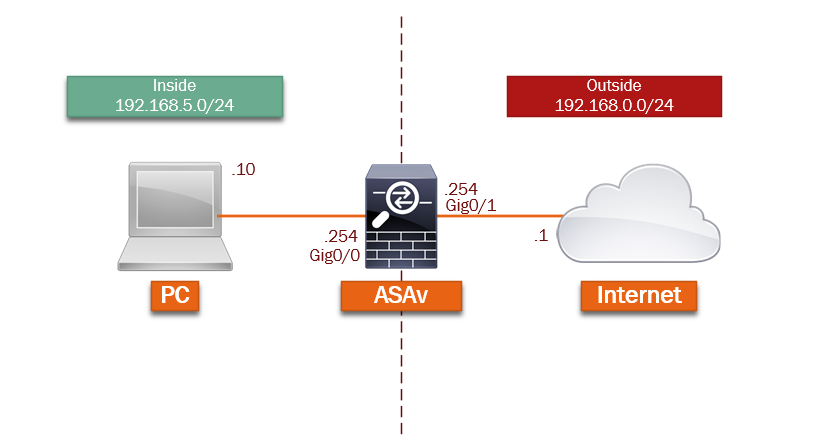
GNS3 is running version “2.0.2” of both the application and VM, which is the latest version at this time.

Lets begin…
Import and Prepare the ASAv
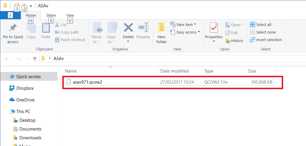
Step 1: From the Cisco website download the Qemu image for the ASAv, this will be the following file: “asav971-1.qcow2”
You will need a service contract to download the file.

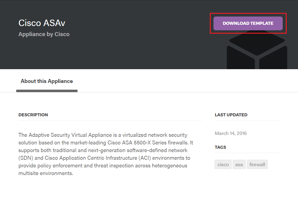
Step 2: Navigate to https://www.gns3.com/marketplace/appliances, search for “ASAv” and
download the ASAv template for GNS3.

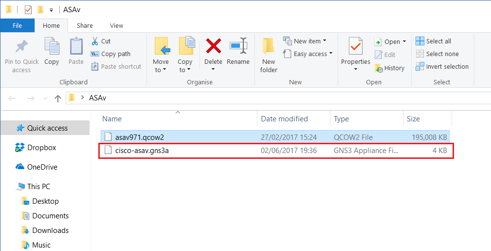
Step 3: From GNS3 click “File-Import appliance”

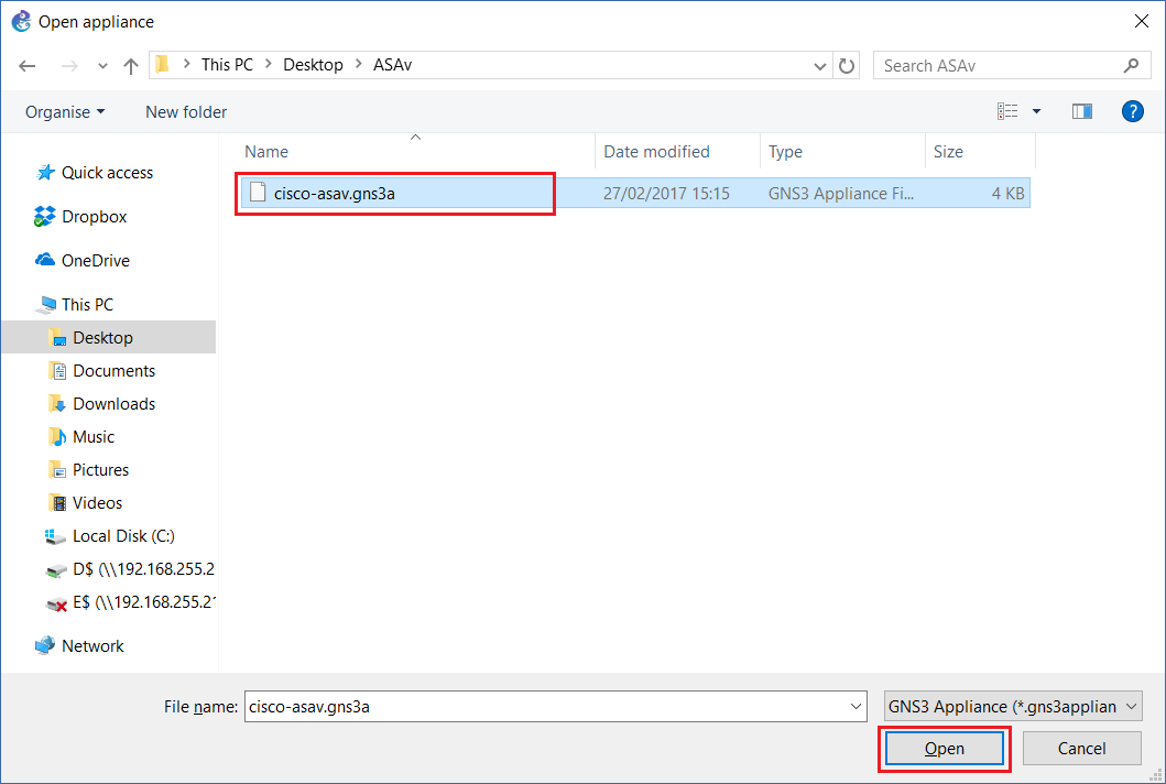
Step 4: Navigate to the previously downloaded file and click “Open”
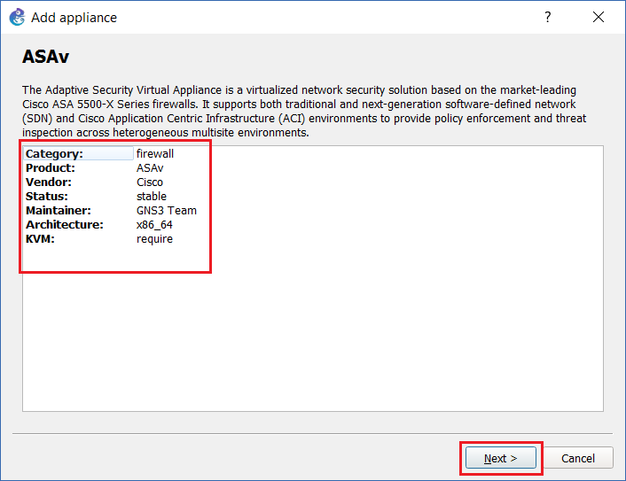
Step 5: At the Wizard verify the correct appliance is listed with the following details as shown below, click “Next”
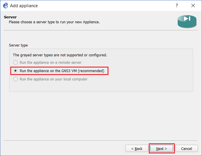
Step 6: The only options for running the appliance will be on the GNS3 VM, click “Next”
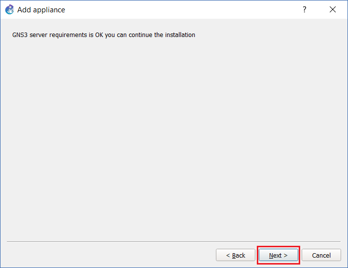
Step 7: Once the requirements have been checked click “Next”
Step 8: GNS3 will automatically look for the Qemu image file and inform you if it is present, as this file is already in the same folder as the appliance this shouldn’t be a problem. Ignore the additional status for “missing files” this is informing that the other versions listed for the ASAv are not present. Click “Next”

Step 9: At the prompt to install the Cisco ASAv click “Yes”

GNS3 will upload the Qemu file to the VM and install the ASAv
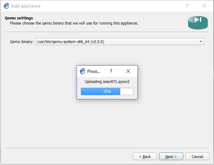
Step 10: At the Qemu binary page, leave the default and click “Next”

Step 11: At the summary page click “Next”

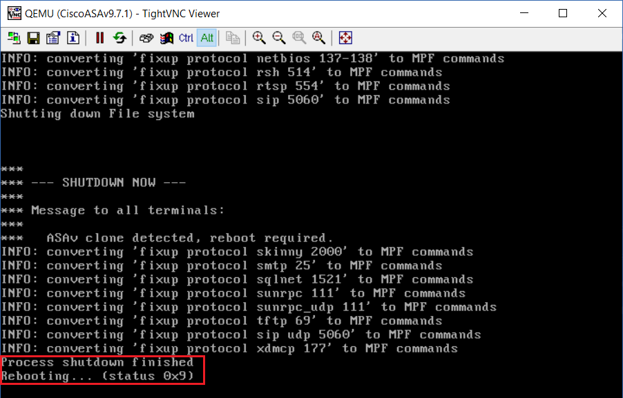
Step 12: The wizard will display the following information – “There is no default password and enable password”. Also note that the device will boot twice as part of the sequence, which is normal and expected. Click “Finish” to close the wizard

Step 13: Click “OK” to close the notification

The ASAv should now be displayed in the left hand pane as a usable device.
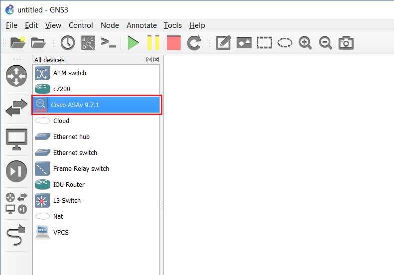
Step 14: Now that the device has been imported, we will need to configure a few additional steps to allow the device to work with our environment. By default, the serial port on the ASAv appliance is disabled, we will need to enable this to be able to use a terminal application software like putty.
Click “Edit-Preferences”

Step 15: Navigate to “Qemu VMs”, select the ASAv and click “Edit”
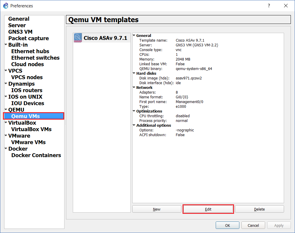
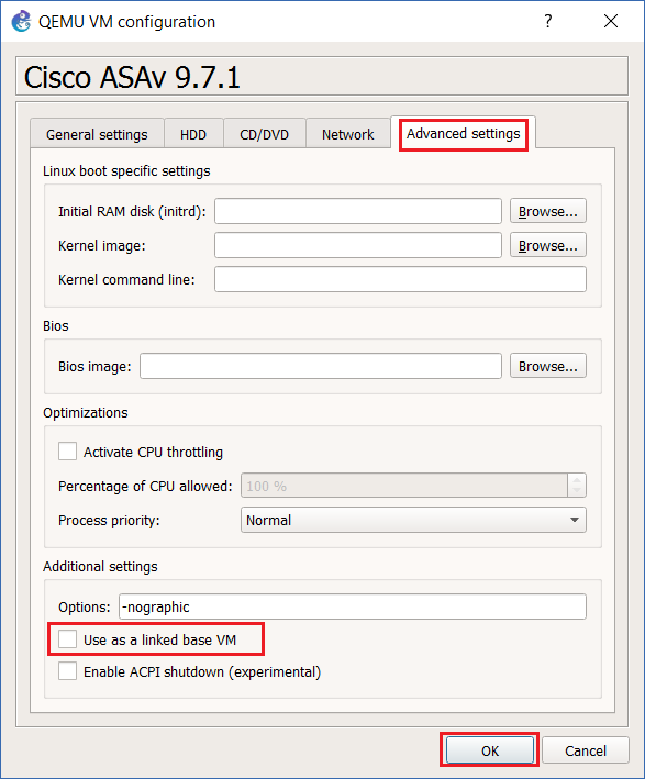
Step 16: Click on the “Advanced Settings” tab and untick “Use as a linked base VM”. (this will be switched back on later) This will allow us to create a working base template to our preference and then save it as a master so that every time we bring out an ASAv into our project it will inherit the settings of the master.
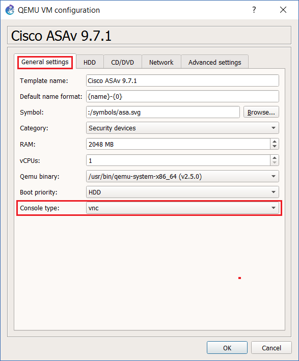
Step 17: Click “General Settings” and select “VNC” as the console type. (this will be switched back to telnet later) Click “OK” to save the changes and close the window.
Step 18: On the GNS3 Workspace click and drag out the ASAv, right click the device and click “Start”

As the device fires up, it will launch using VNC, select the first option and let the device go through boot process.
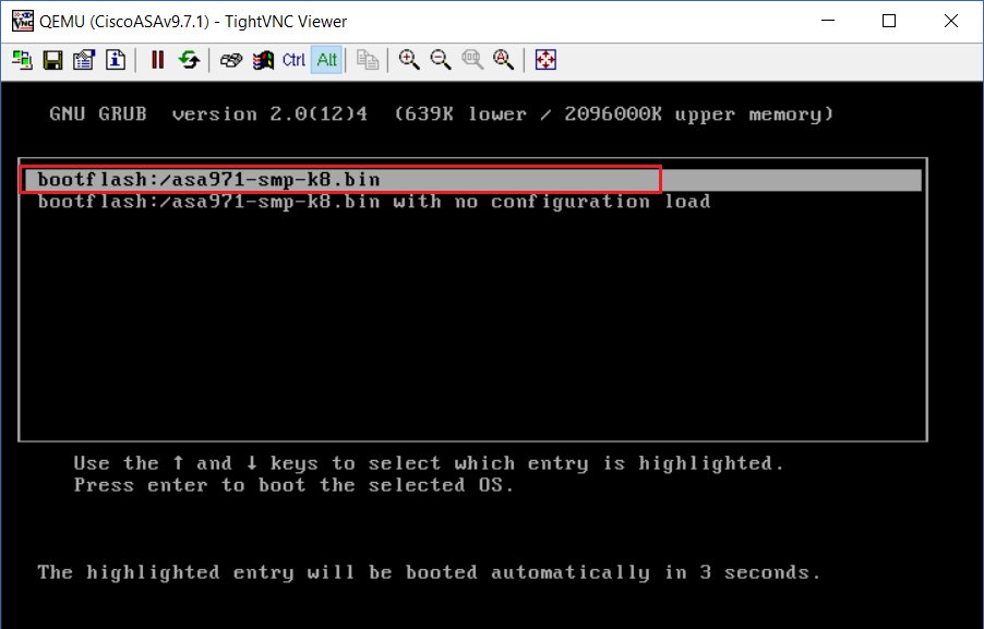
The device will power cycle two times as mentioned earlier.
The device will now show the “ciscoasa>” prompt, this indicates the ASAv is ready, Type “Enable” and hit enter, the device has no password set.

Step 19: Lets configure the device to use serial as its method of connection, to do this we need to create a file inside the flash called “use_ttyS0” The easiest way to add this is to clone the existing \coredumpinfo\coredump.cfg file and rename it.
#conf t
#cd coredumpinfo
#copy coredump.cfg disk0:/use_ttyS0 – (S=Snooping, 0 = Zero)
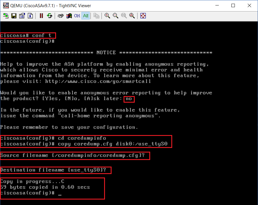
Step 20: Verify the file has been created and exists in the file system.
#dir disk0:/
As we can see below “use_ttyS0” is present, now we need to reboot the ASAv –
#reload (there is no need to save the config)

Once the device reboots, it should halt at and display “Lina to use serial port /dev/ttyS0 for console IO”, indicating its transferred the interactive control to the serial port.
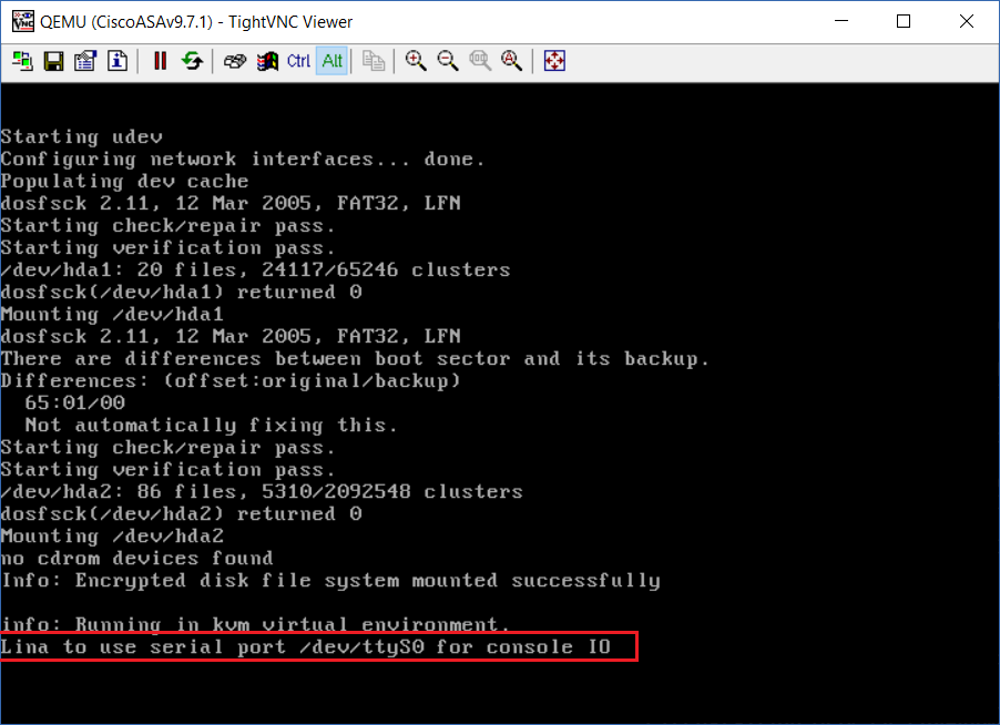
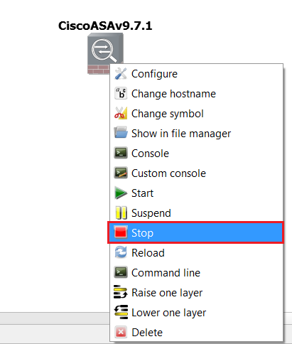
Step 21: It’s now time to change the console from “VNC” back to “Telnet” and lock the ASAv so this becomes the master template. This way we don’t have to re-configure the serial port each time we bring out a new ASAv.. Power off the ASAv by right clicking and selecting “Stop”.
Step 22: Delete the ASAv from the project by right clicking the device and selecting “Delete”

Step 23: From GNS3, Click “Edit-Preferences”
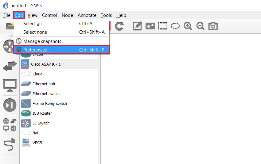
Step 24: Select “Qemu VMs”, select the ASAv and click “Edit”
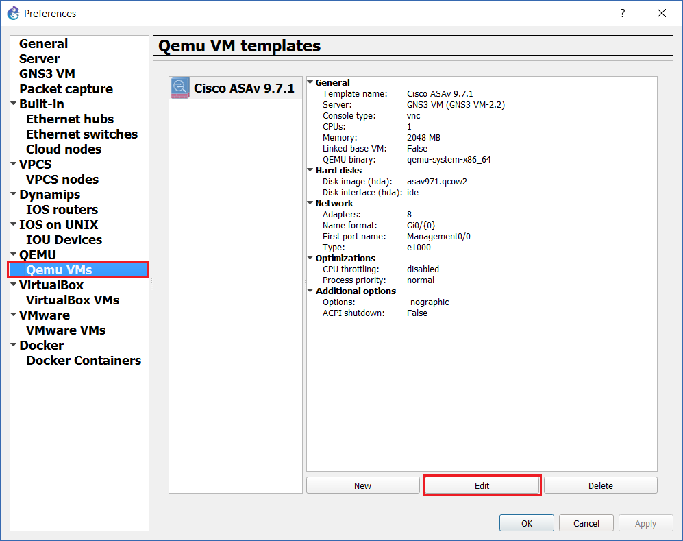
Step 25: From the “General Settings” tab, under “Console type” select “telnet”

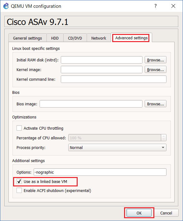
Step 26: Click the “Advanced” tab, and tick “Use as a linked base VM” and click “OK”
Step 27: Create a new project, save it and drag out a new ASAv. Right click the device and select “Start”

Double click the device to bring up a console session, this should now open with Putty, (the screen may appear blank for up to 30 seconds, this is normal) once the device boots up the “ciscoasa>” prompt will be displayed.
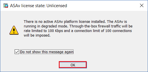
As the device is not yet licensed it will keep prompting this – every few minutes, this is not a major issue as we can still use it in a lab environment to test out different features. The only restriction this device will have is on the throughput which is capped at 100Kbps, and up to 100 maximum connections.
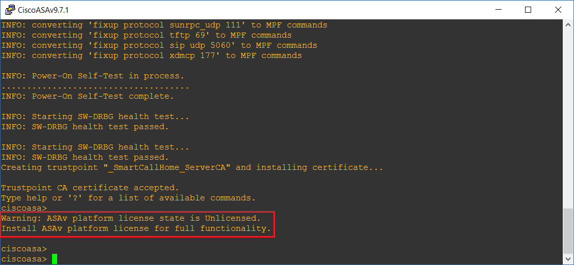
Step 28: let’s take a look at the spec and features of the device as it is and also without a valid licence –
#show version
We can see the following from the output –
The ASA version is 9.7(1)
The Firepower version is 2.1(1.66)
The ASDM Version is 7.7(1)
We can see the device spec in terms of hardware
The device has 8 Gigabit Ports
The platform is unlicensed is capable of using the following features:
10 Total interfaces
Maximum of 50 VLANs
Unlimited Inside Hosts
Active/Standby Failover
2 VPN Any connect
250 VPN peers
Botnet Traffic Filter

Configure Basic Management Capability & install ASDM
Step 1: in order to manage the ASAv using ASDM we would need to gain management access to the device, to do this we can either configure the “Managment0/0” interface if we have a dedicated management VLAN (which could be bridged to a VMnet, if inside VMWare) or any other interface that will be assigned to the “Inside Zone”
In this example we will use “Gig0/0” as this will be assigned to the “Inside” zone.
#enable
#conf t
#interface gig0/0
#ip address 192.168.5.254 255.255.255.0
#no shut
#nameif Inside
#exit

Step 2: From the “PC” ping the interface “Gig0/0” interface

Step 3: Enable https access to the device to allow ASDM to connect to it from the “Inside” zone
#https server enable
#http 192.168.5.0 255.255.255.0 Inside
#wri me – save the changes

Step 4: from the “PC” Launch a browser and navigate to https://192.168.5.254, Click “Continue to this webpage (not recommended)”. The device is using a self-signed certificate therefore the browser will not trust this.

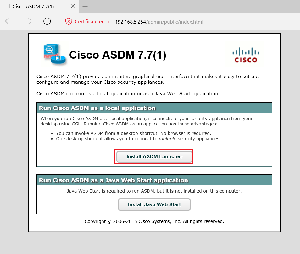
Step 5: We should now be presented with the Cisco ASDM page, click “Install ASDM Launcher” to download the asdm installer (a prerequisite for the ASDM launcher is to ensure you have the latest version of “Java Runtime Environment”)
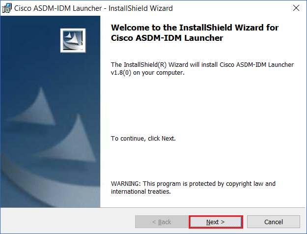
Step 6: Run the installer, At the Wizard Click “Next”
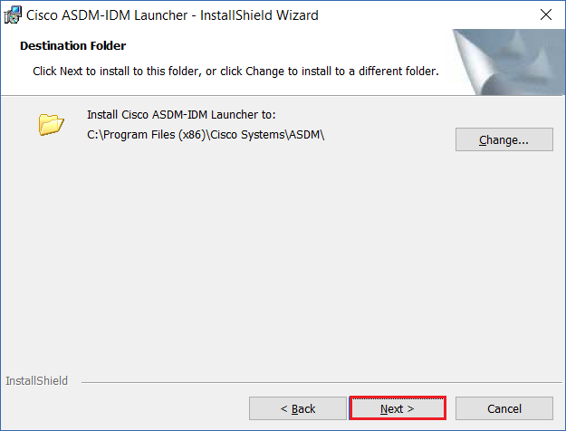
Step 7: Leave the default installation directory and click “Next”
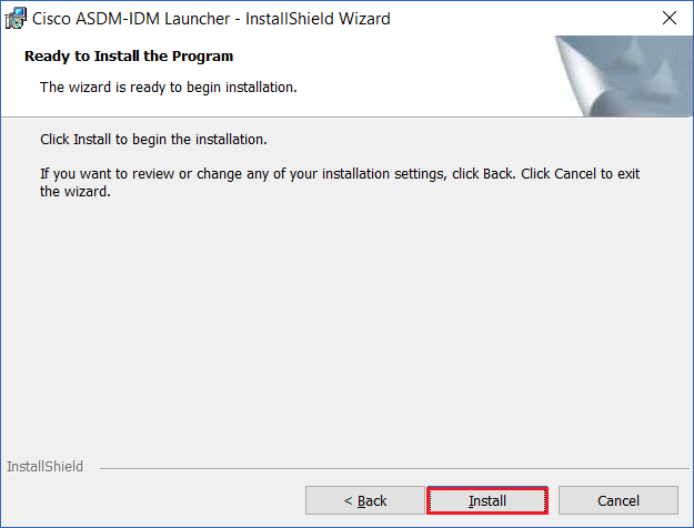
Step 8: Click “Install”
Step 9: At the UAC prompt click “Yes”

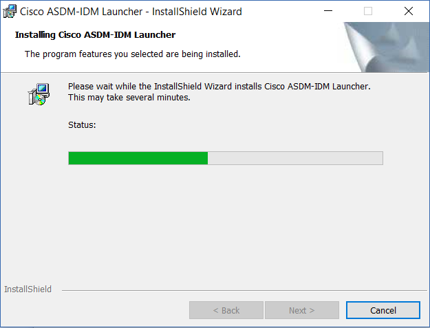
The installation will begin.
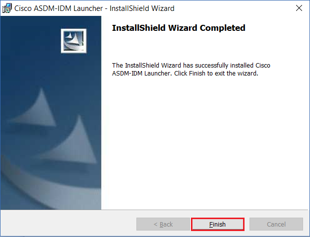
Step 10: Click “Finish” to close the wizard
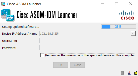
Step 11: ASDM should load automatically, if it doesn’t – launch it from the start menu. Insert the IP of the ASAv’s Inside interface and click “OK”

Step 12: At the security warning, click “Continue”

ASDM will load
ASAv Licence prompt will be displayed, click “OK” to close
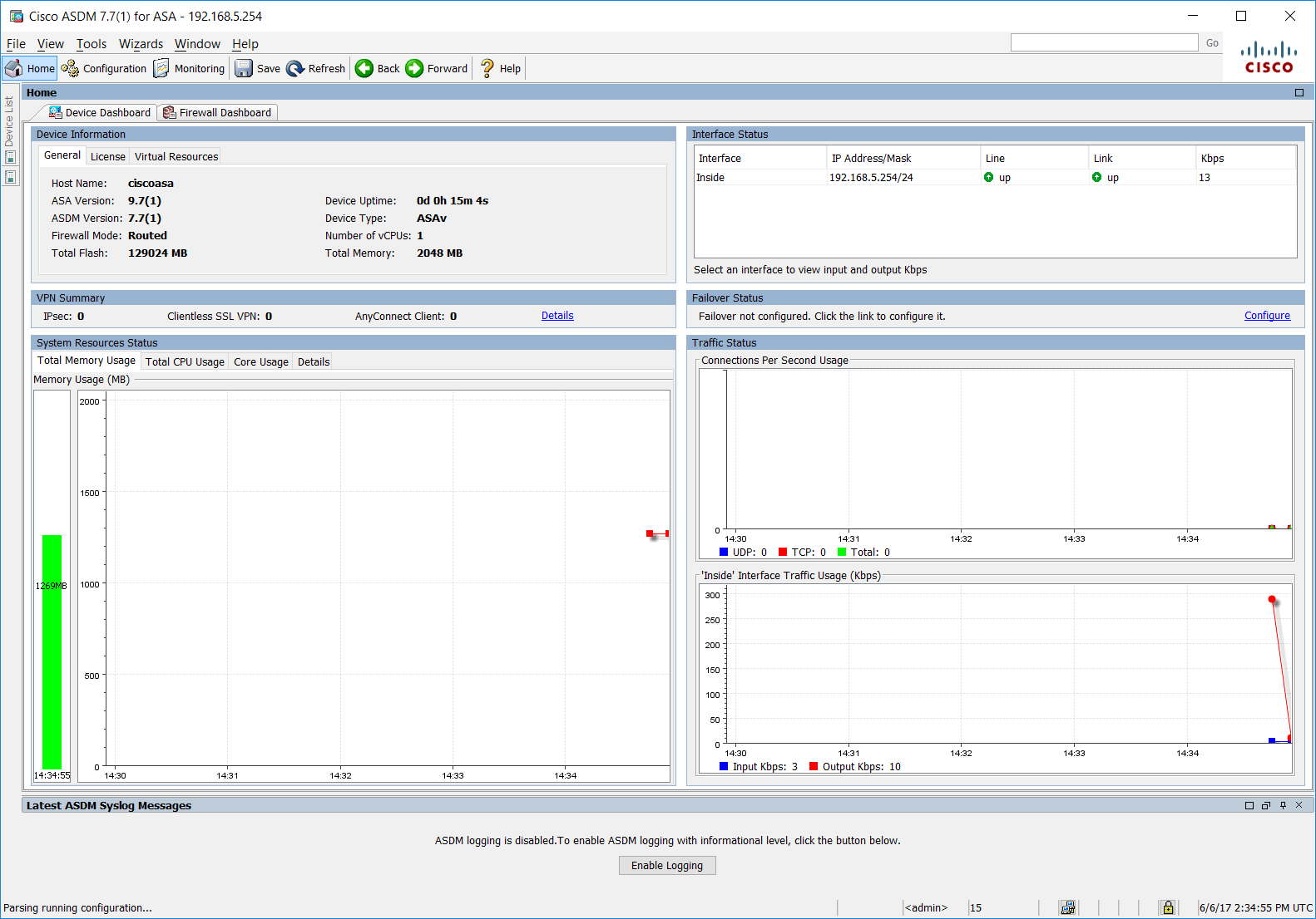
Step 13: Once ASDM opens we should see the full GUI management interface as shown below.
Integrate the ASAv to the physical network
Now that we have setup the ASAv with full management capability from both ASDM and the CLI, we can pretty much start configuring the firewall. As an additional step Lets configure the ASAv’s outside interface and integrate it to our local LAN, which routes out to the internet. Remember we do not have NAT configured so the “PC” won’t be able to get out, Ill cover NAT on a separate post, but as for the ASAv, we should be able to reach the physical network and the internet using its outside interface.
There are several ways of integrating GNS3 devices into the physical network, we could use a loopback interface and bind it to a physical adaptor to share the internet connection or we could simply create additional NIC interfaces on our GNS3 VM and allocate those to “VMNets” within VMware – this method has been the most reliable in my opinion and connectivity is pretty solid without any drops in traffic. Whereas using the loopback can cause basic connectivity issues which can result in hours of troubleshooting.
Step 1. Lets bind the physical adaptor of the host to the logical VMNet. Launch VMWare workstation and select “Edit” and “Virtual Network Editor”

Step 2: as we can see from the list of networks, “VMNet0” isn’t being displayed, this is usually the logical adaptor that binds to the physical adaptor, to view and edit this, click “Change Settings”
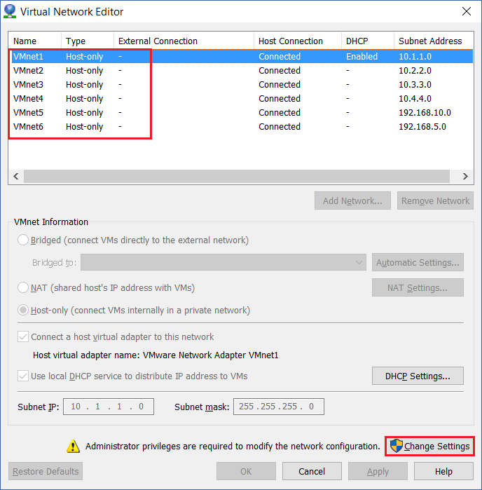
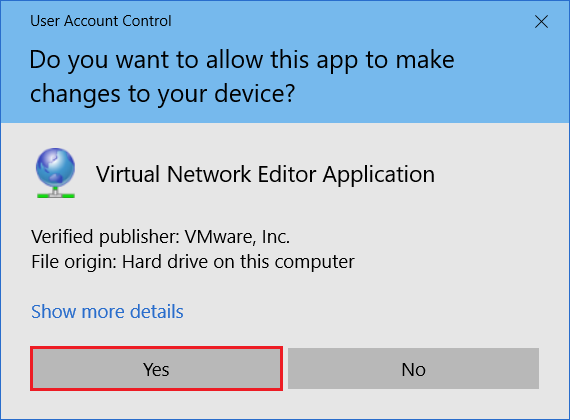
Step 3: Click “Yes” to Accept the UAC prompt
Step 4: Select “VMNet0” and allocate it to the physical adapter of your choice, this will be the adapter that connects to the physical network. In this case I have used the “Wi-Fi” adapter. Click “OK”

Step 5: Now we need to create a new NIC on the GNS3 VM and allocate it to “VMNet0”, right click the “GNS3 VM” and select “Settings”

Step 6: Under the “Hardware” tab, click “Add”

Step 7: Click “Yes” at the UAC prompt

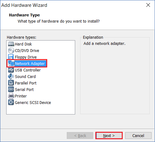
Step 8: Select “Network Adapter” and click “Next”
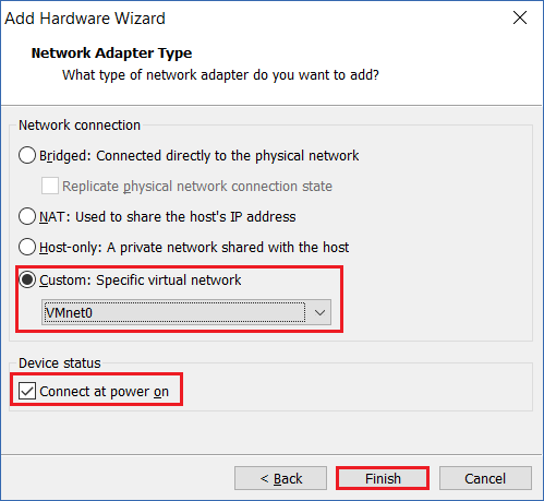
Step 9: Select “Custom: Specific virtual network” and select “VMNet0” from the list. Tick “Connect at power on” and click “Finish”
Step 10: Click “OK” to close the window.
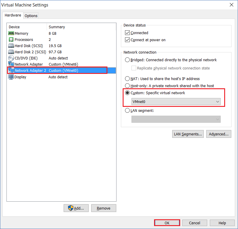
Step 11: GNS3 will need to be closed and re-opened for the changes to be visible, save the changes on the ASAv using “Write Memory”, save the project, close GNS3 and re-launch the application.
Once the project has been re-opened and devices powered up, drag a new “Cloud” from the left hand pane onto the workspace.
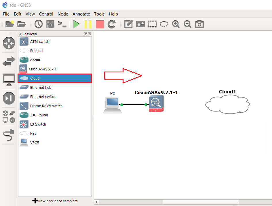
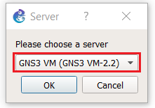
Step 12: At the prompt for where to run the “Cloud” from, Select the “GNS3 VM”
Step 13: Using the link tool connect the ASAv’s “Gig0/1” interface to the “Cloud” which is the newly created interface on the “GNS3 VM” in this case its “Eth1” (Eth0 belongs to the GNS3 VM itself)


Step 14: On the ASAv configure the “Outside” interface
#conf t
#int gig0/1
#ip address 192.168.0.254 255.255.255.0
#no shut
#nameif Outside
#exit

Step 15: From the host machine, (while connected to the physical network) test the “Outside” IP address of the ASAv is reachable. As we are connected to the physical network using “Wi-Fi” we should be able to reach the IP as it’s on the same broadcast domain.
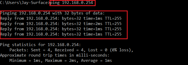
Step 16: If we ping from the ASAv using the “Outside” interface we should be able to reach the real default gateway on the physical network.
#ping outside 192.168.0.1

Step 17: At this moment if we try and ping out to the internet, we wouldn’t be successful. And the reason for this is – we don’t have a default gateway/default route configured for the ASAv
#ping Outside 8.8.8.8

Step 18: Lets give the ASAv a default route
#route Outside 0.0.0.0 0.0.0.0 192.168.0.1
![]()
Step 19: We should now be able to ping 8.8.8.8 successfully
#ping Outside 8.8.8.8


