Deploying a Checkpoint Firewall Solution (GAIA-R77.30)
Checkpoint is known as being a next generation firewall vendor due to being able to support advanced features up to layer 7 of the OSI model, these include “Application Filtering”, “Deep Packet Inspection(DPI)”, “IPS”, “SSL Inspection”, “AV scanning”, “Identity Management”, “URL Filtering” and many more.
Checkpoint Firewalls are not zone based Firewalls unlike your Cisco or Juniper. These firewalls can either be physical or virtual. the main differences between the two types is that physical devices have the hardware capability to perform at much higher levels compared to the VM instances. However they all have the same software versions available to run either on physical hardware or as a virtual machine.
Checkpoint firewalls are managed in a different way in comparison to other vendors, to manage a “Security Gateway” you need to use a “Management Server”, and in order to use the management server you need to use “Smart Tools”, these tools consist of “Smart Dashboard”, Smartview Tracker”, Smartview Monitor”, SmartDomain Manager” and a few others. The tools are normally installed on a workstation which then connects to the management server to create and manage policies. The polices are then installed on the security gateway.
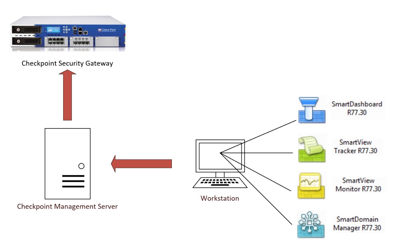
You can run a “Management Server” from a physical firewall appliance, a windows machine or a virtual appliance running the OS GAIA.
The management server in most cases is another GAIA appliance with capability for logging, there are options to deploy a gateway and management server in one appliance, this is known as a distributed deployment.
In this step by step guide we will run through the process of deploying a checkpoint security solution, using R77.30. We will first deploy a “Security Management Server” and install the “Smart Tools” on a workstation. Then we will deploy a separate appliance that will be the “Security Gateway” and add it into the management server to be able to install security polices. For this Lab we will use VMware ESXI, the same concepts apply to physical firewalls, in most cases they come pre-built with the latest software so its just a matter of assigning a management IP to the device and running through the web GUI configuration.
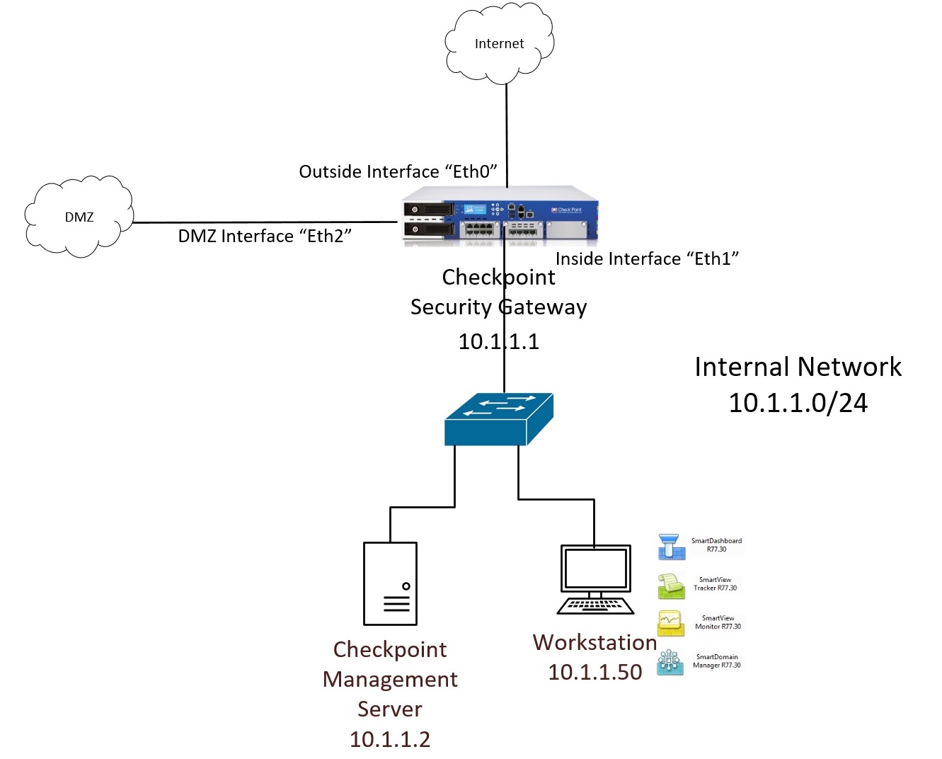
The Topology:
Anchor Links:
Lets get started!
Deploy the Management Server
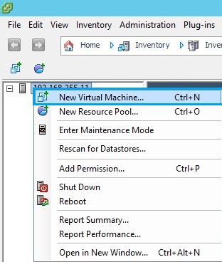
1. From vSphere, right click the host and select “New Virtual Machine”
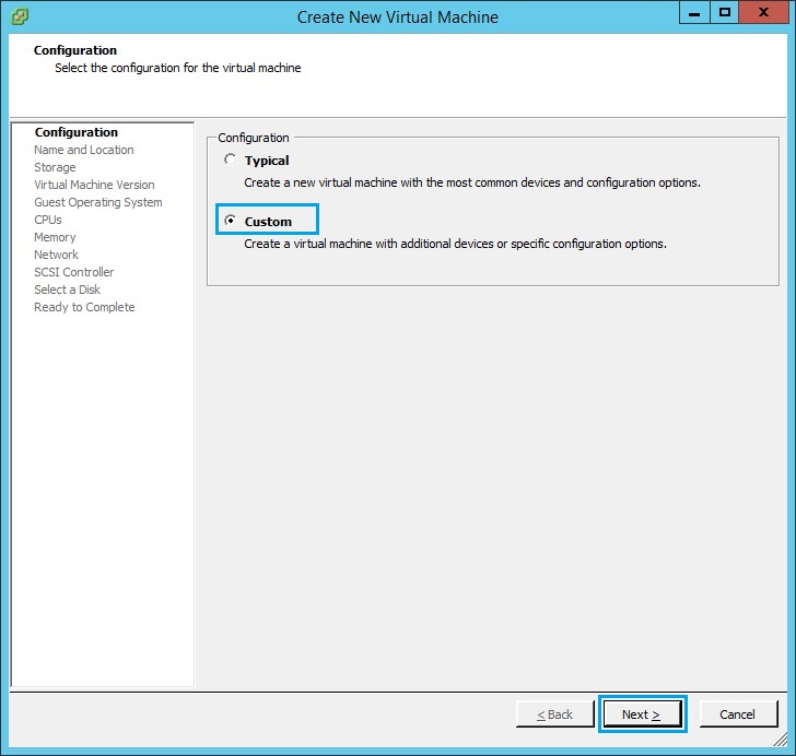
2. Click Custom and click “Next”
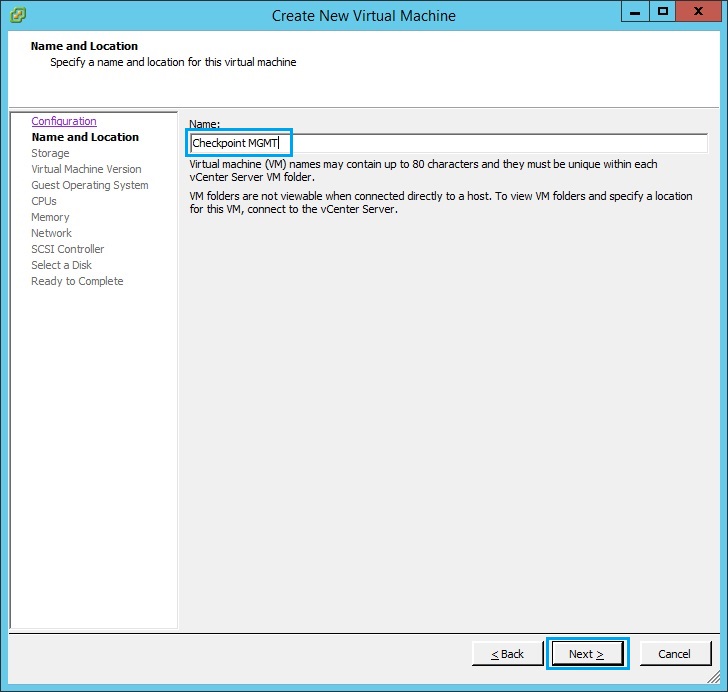
3. Give the VM a name and click “Next” – as this will be the management server i have called it “Checkpoint MGMT”
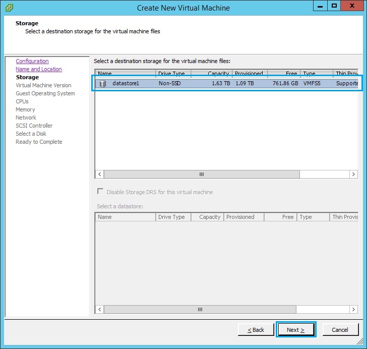
4. Select the data store to store the VM and click “Next”
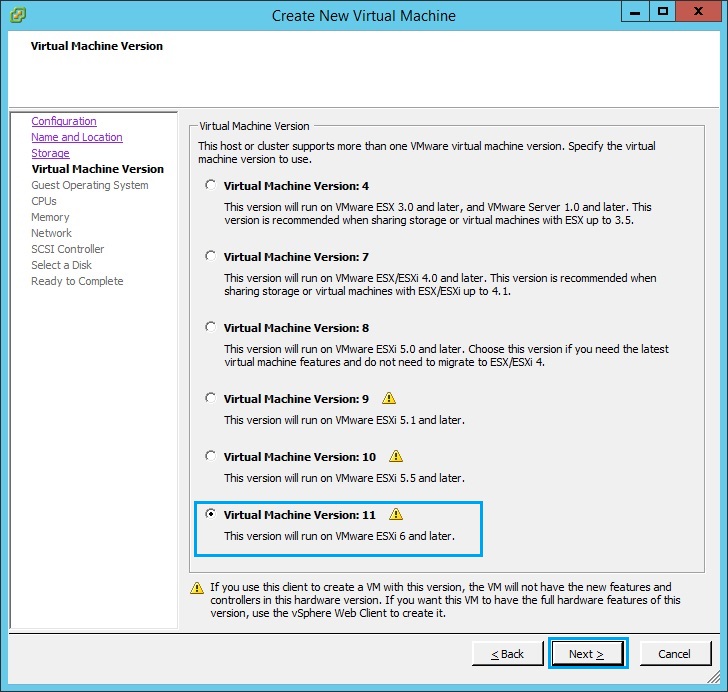
5. Select “Virtual Machine Version: 11” and click “Next”. If your ESXI is below version 6 use version 10.
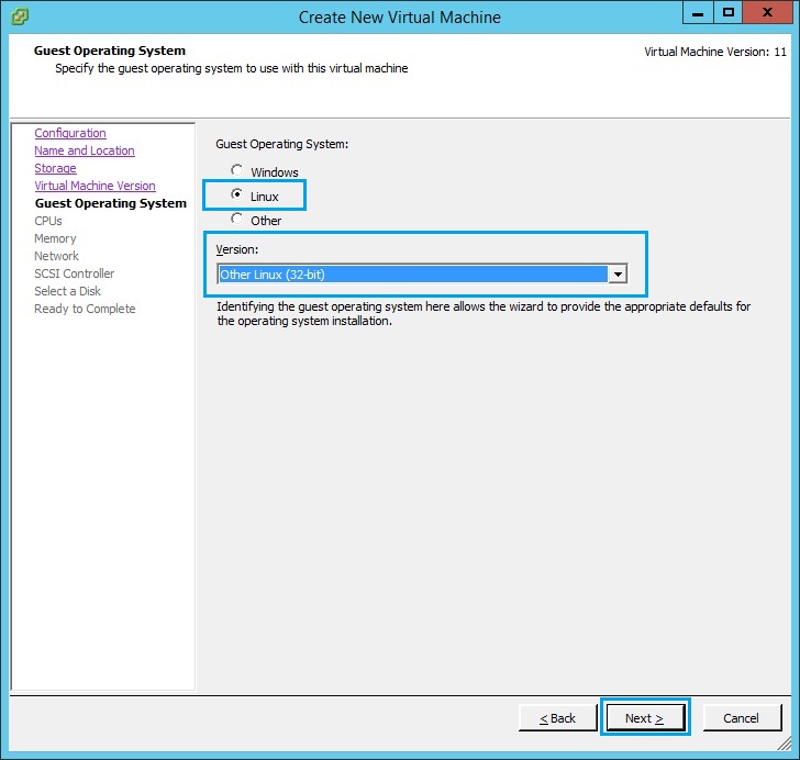
6. Select “Linux” as the guest operating system. From the drop down menu select “Other Linux (32 bit)” as the “Version”
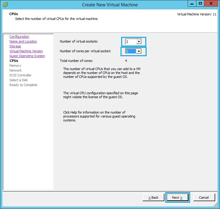
7. Assign the VM CPU according to the hardware capability of the ESX host. In this case i have assigned “2 Virtual sockets” and “2 Cores per socket”. Click “Next”
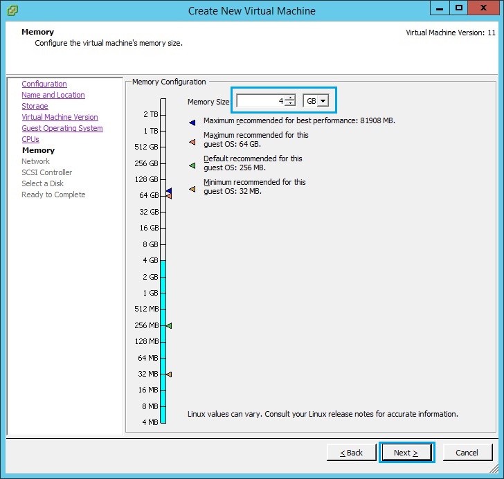
8. Give the VM a minimum of 4GB RAM and click “Next”
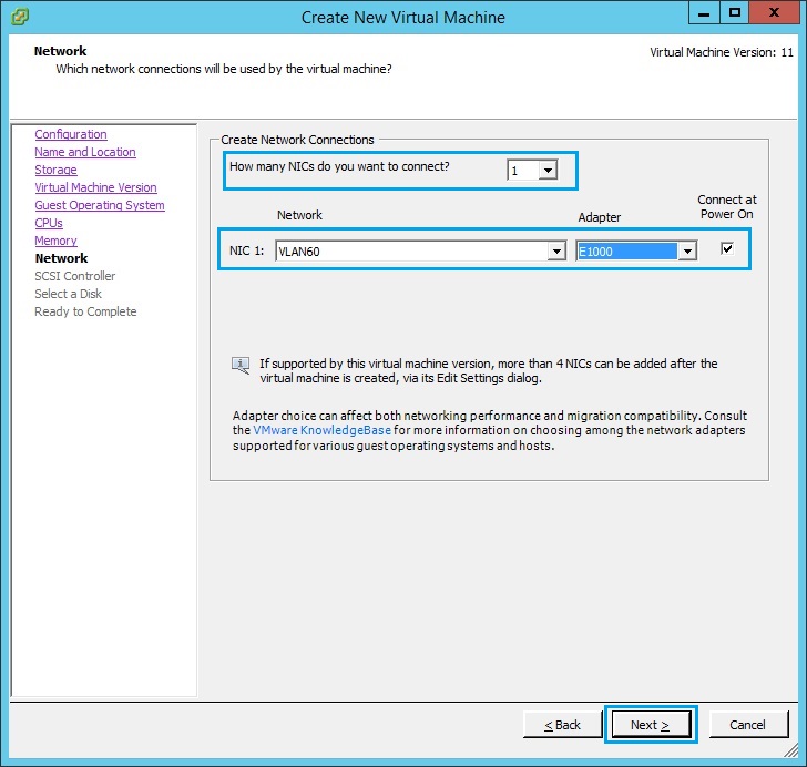
9. Give the Management server 1 NIC and assign it to the appropriate VLAN on the inside network. In our case this is “VLAN60”, we need to be able to reach this management server from the workstation which will also be on VLAN60 and have the smart tools installed. Click “Next”
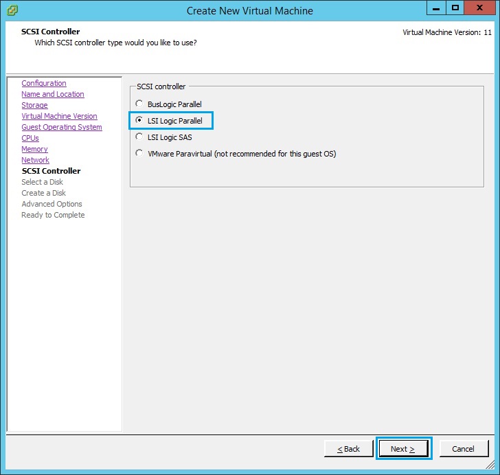
10. Select “LSI Logic Parallel” and click “Next”
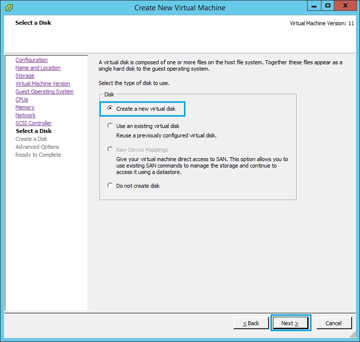
11. Select “Create a new virtual disk” and click “Next”
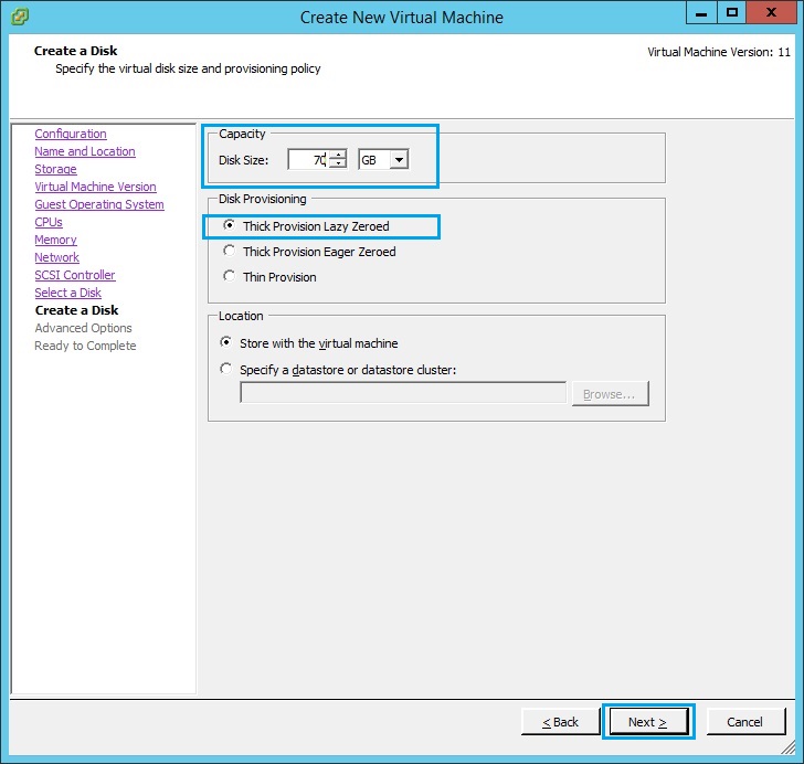
12. Specify the size of the disk in GB, make sure the size is at least “70GB” as the logs will be stored on this device and the disk space could fill up quick. Select “Thick Provision Lazy Zeroed” and Click “Next”
13. Select “SCSI (0:0)” and click “Next”
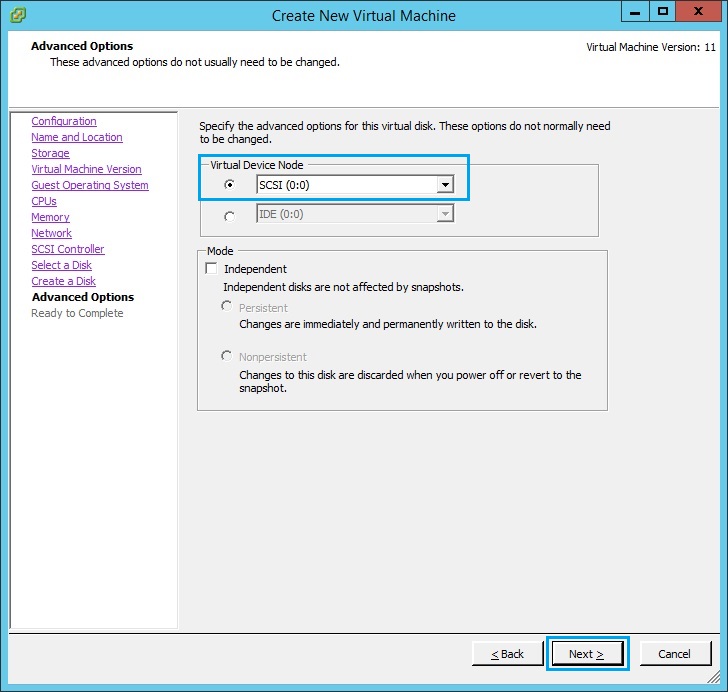
14. At the summary screen, verify all the details are correct, tick “Edit the virtual machine settings before completion” and click “Continue”
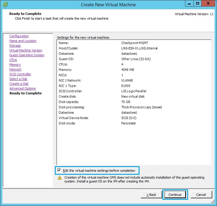
15. From the “Virtual Machine Properties” select “New CD/DVD (adding)”. Tick “Connect at power on” , select “Datastore ISO File”. Click “Browse”
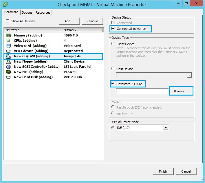
16. Browse the datastore and select the Checkpoint ISO image, (This will need to be uploaded prior to creating the VM). Once selected click “OK”
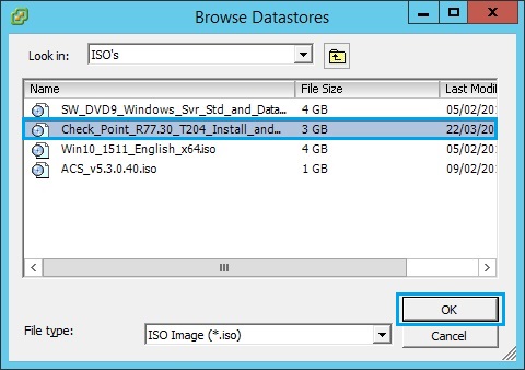
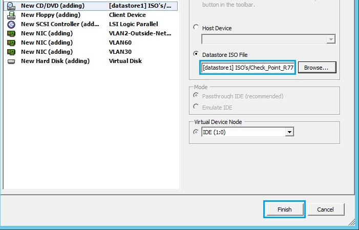
17. The ISO should now be present inside the Datastore ISO File field. Click “Finish”
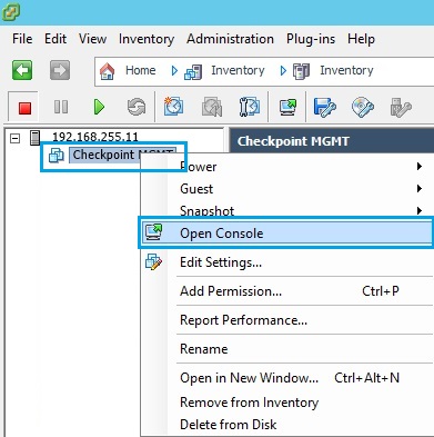
18. Once the VM has been created, right click the VM and select “Open Console”
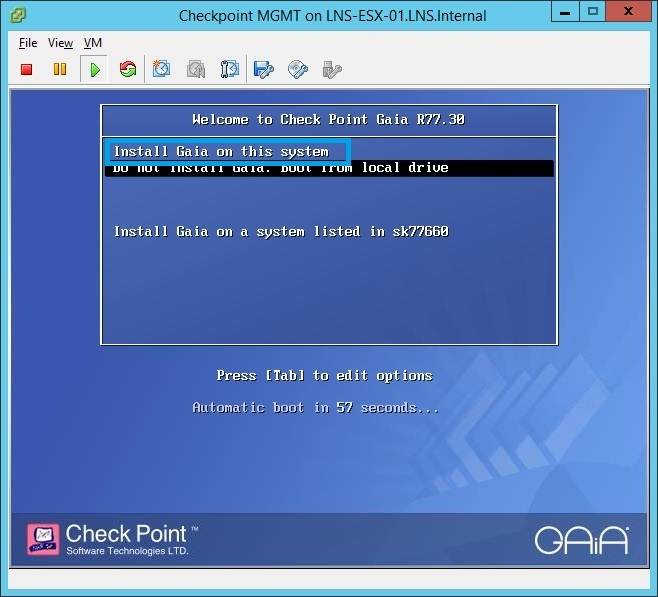
19. Click the green “Play” button to power on the virtual machine. As the VM boots, it will load the specified checkpoint ISO, select “Install GAIA on this system”
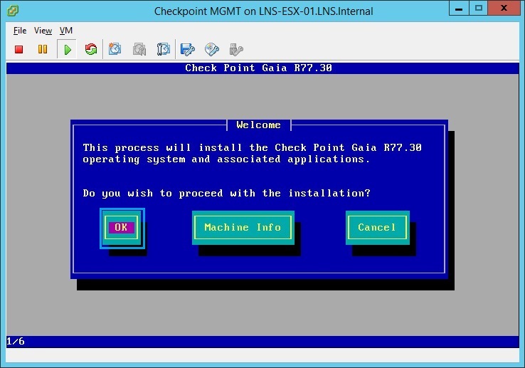
20. At the “Welcome” screen select “OK” to proceed with the install.
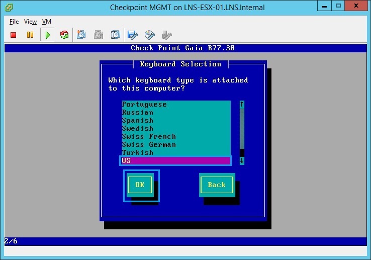
21. Select “US” and click “OK”
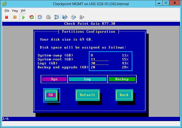
22. Allocate 40% of your disk space for “Logs (GB)” and select “OK” in this case 30GB is around 43%.
23. Create the “admin” password and click “OK”

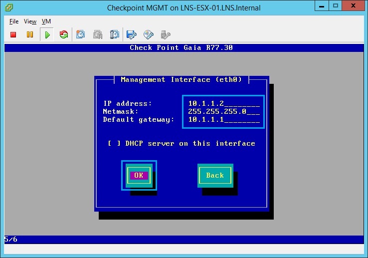
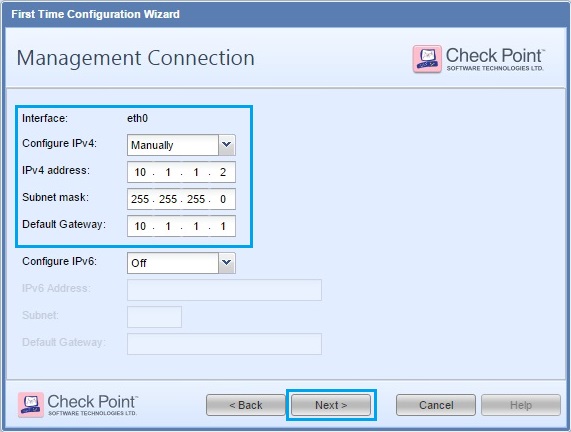
24. Give the Management server an IP address, in this case we have used – “10.1.1.2/24” and 10.1.1.1 as the default gateway which will be the setup later as the “Security Gateway” Click “OK”
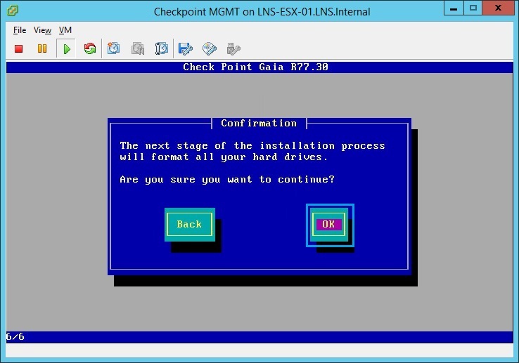
25. At the confirmation screen click “OK”, the device will reformat the HDD and install the GAIA OS.
26. Once installation is complete the device will prompt to “Reboot” click “Reboot”
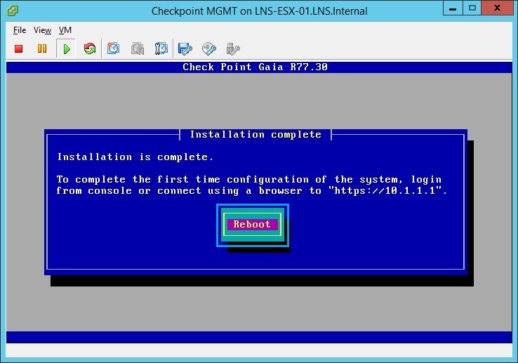
27. once the system as rebooted and is ready it will display the logon prompt

28. From a workstation that is able to reach “VLAN60” Launch a browser and navigate to “https://10.1.1.2” at the warning prompt, click “advanced” and click “Proceed to 10.1.1.2 (unsafe)”
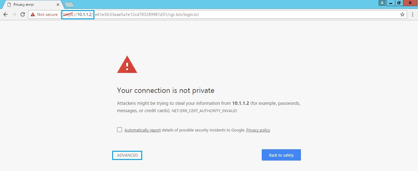
29. at the login prompt for “GAIA” use the username “admin” and the password that was set at the previous step.
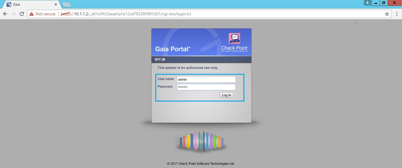
30. Once logged in, the device will display a “First Time Configuration Wizard” to complete the initial setup. At the prompt click “Next”
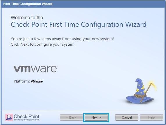
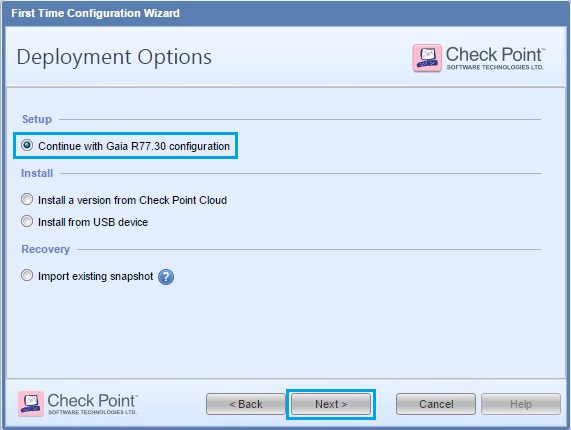
31. Select “Continue with Gaia R77.30 configuration” and click “Next”
32. Verify the IP address details are correct and click “Next”
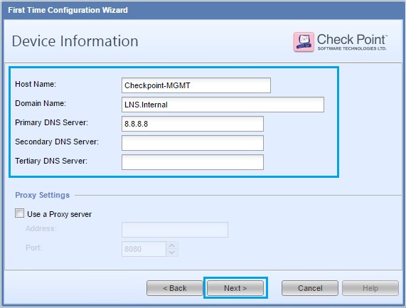
33. Give the device a “Host Name”, “Domain Name” and “DNS server” details. Click “Next”
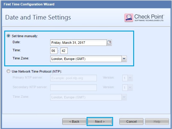
34. Ensure the time setting are correct and click “Next”
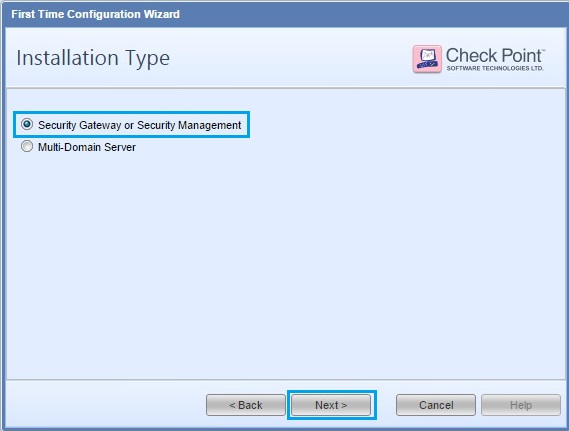
35. Select “Security Gateway or Security Management” Click “Next”
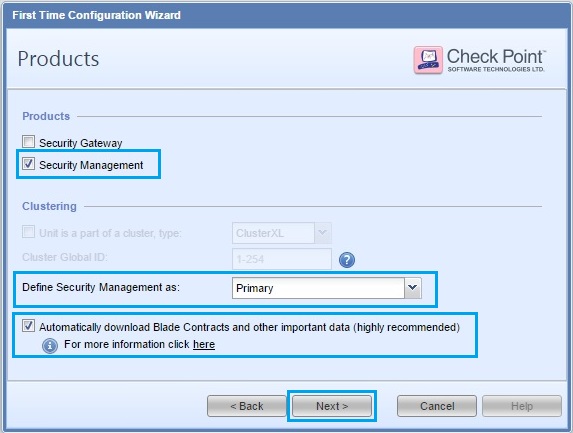
36. From the checkbox option, select “Security Management” set the device as “Primary” and check the “Automatically download Blades Contracts and other important data (highly recommended)” box. Click “Next”
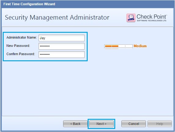
37. Create an Administrator user for the “Management Server” this account is different to the “admin” account. The admin account has privileges for SSH and web GUI access to the device itself, where as the administrator account will be the main account to be used with the “Smart Tools”. Click “Next”
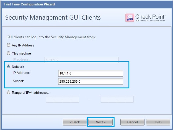
38. At this screen we can define which devices can connect to the “Management Server” we can simply allow any IP addresses or a specific subnet. In this case we will only allow the “10.1.1.0/24” network. Click “Next”
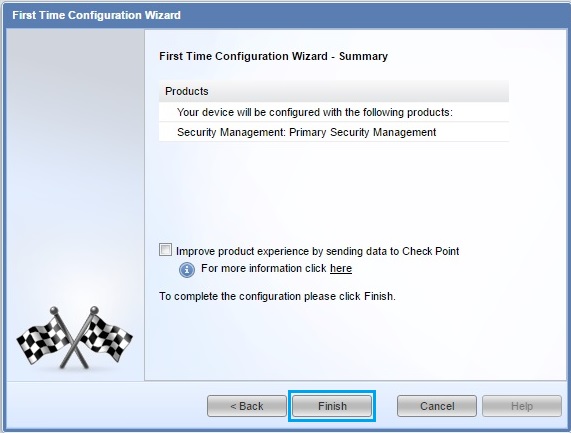
39. Click “Finish” at the summary screen to begin configuration.This process will take a few minutes to complete.
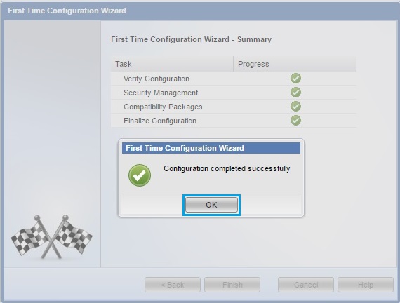
40. Once the configuration is complete click “OK”
41. The device will automatically log in to the web GUI.
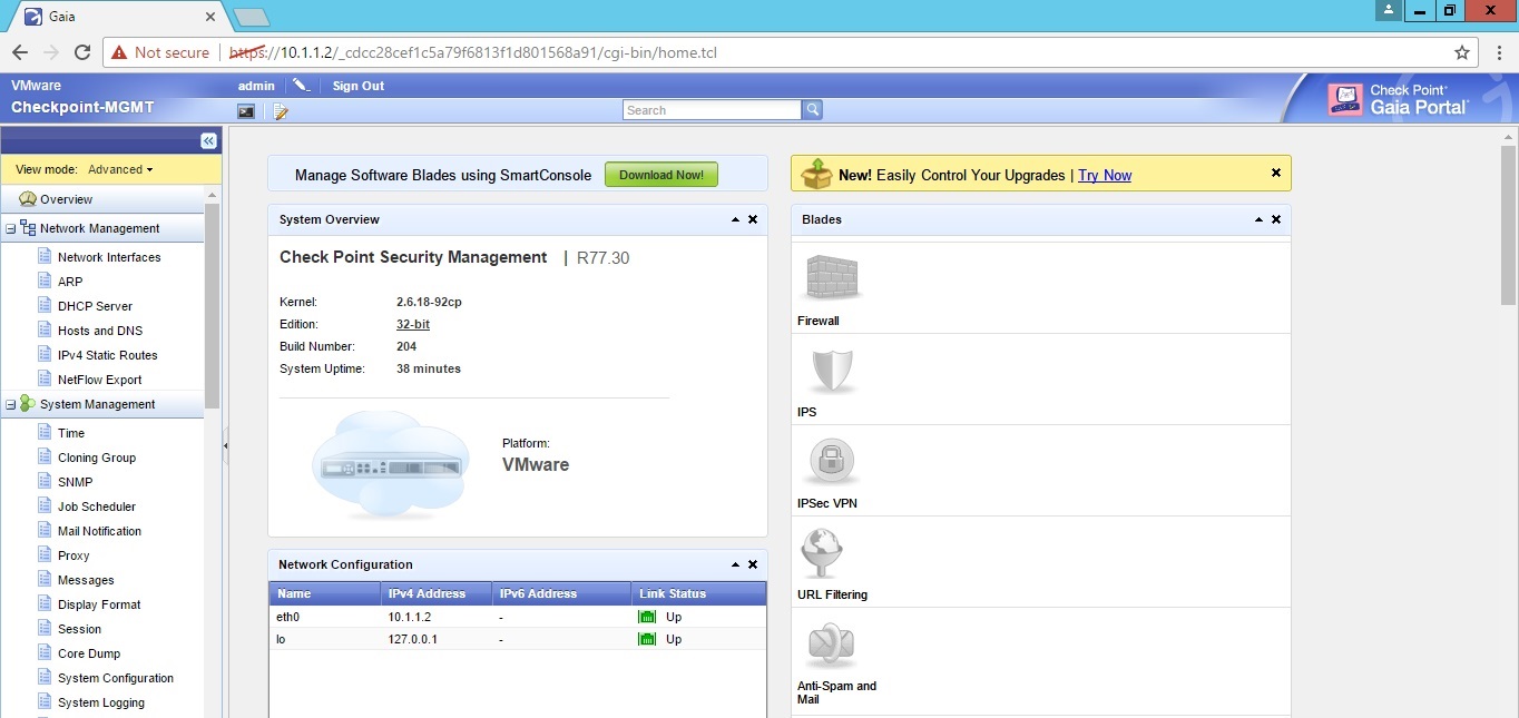
The “Management Server” Installation and configuration is now complete. the next step is to install the smart tools on to a workstation.
Install the Smart Tools
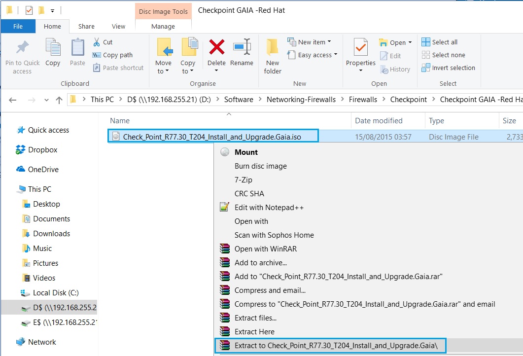
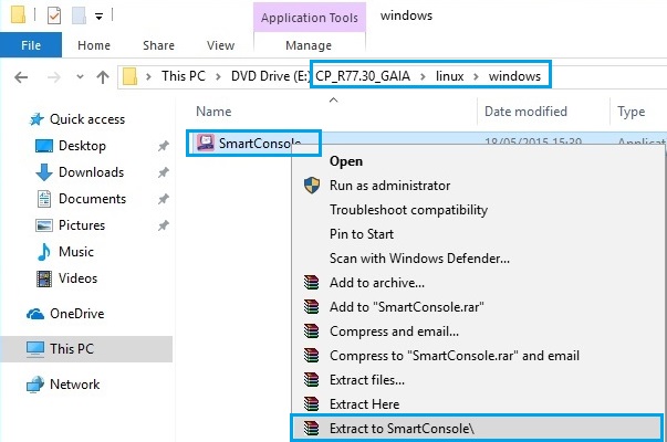
1. Navigate to the “Checkpoint GAIA ISO” on the Workstation that will be used to connect to the “Management Server” right click the .ISO image and extract the contents to a new folder.
2. Once the files have extracted navigate within the extracted folder into “Linux-windows”. Right click “SmartConsole” and again extract the contents into a new folder.
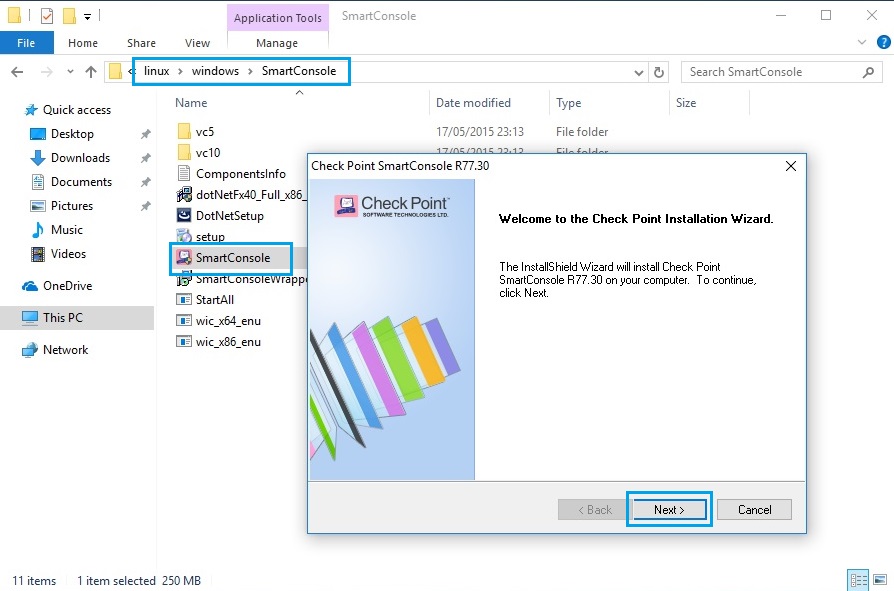
3. From the extracted contents double click “SmartConsole” and run the installation wizard. At the Wizard “Welcome” prompt click “Next”
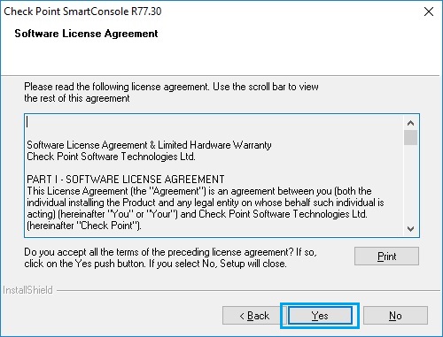
4. At the UAP Click “Yes”
5. Click “Next”
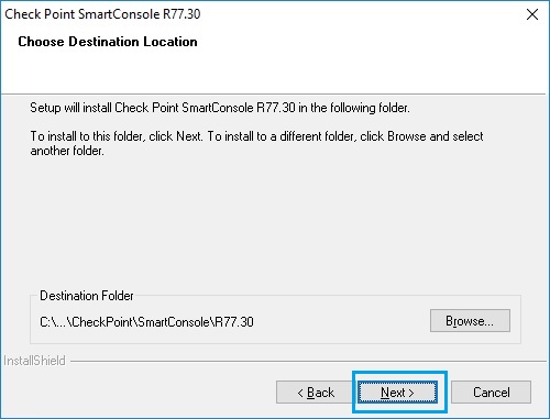
6. Leave the default settings as is to install all the smart tools and click “Next”

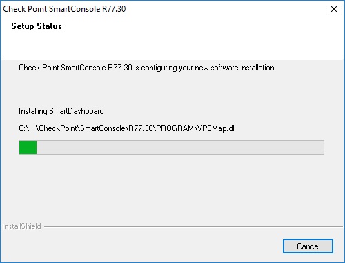
7. the installation process will begin and take around two mins to complete.
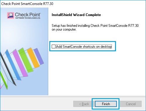
8. Once the installation is complete, tick the checkbox “Add Smartconsole shortcuts on desktop” and click “Finish”
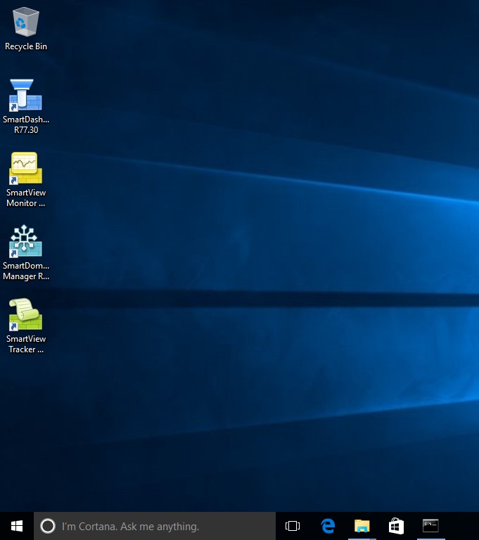
9. The tools should now be visible on the desktop. Click and launch “SmartDashboard” form the desktop. this is the main tool used to connect to the management server.
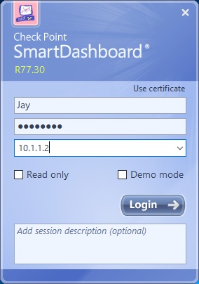
10. At the prompt for login, Specify the “Administrator” login details. And use the IP address of the management server, “10.1.1.2”. Click “Login”
11. The device will display the fingerprint, verify this is correct to ensure you are connecting to the right device.
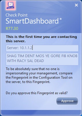
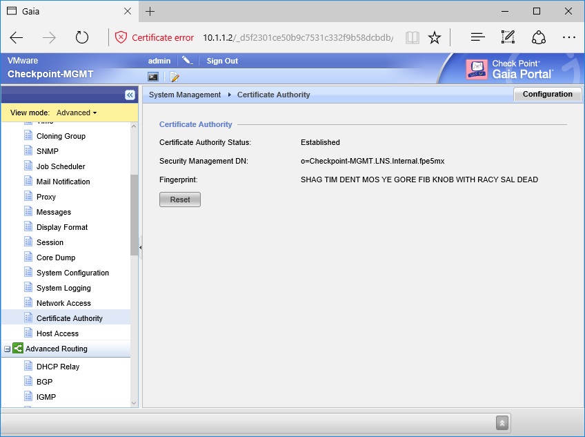
12. Log into the web GUI from a browser at “https://10.1.1.2”. Navigate to “Certificate Authority” and verify the fingerprint matches to the one displayed on smart dashboard. If this matches (Which it should) click “Approve” on smart dashboard to connect.
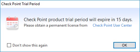
13. The device will display the trial message. Click “OK”
14. Once the user is logged in, “SmartDashboard” will display the the management interface. We can see that there are no “Security Gateways” to manage.
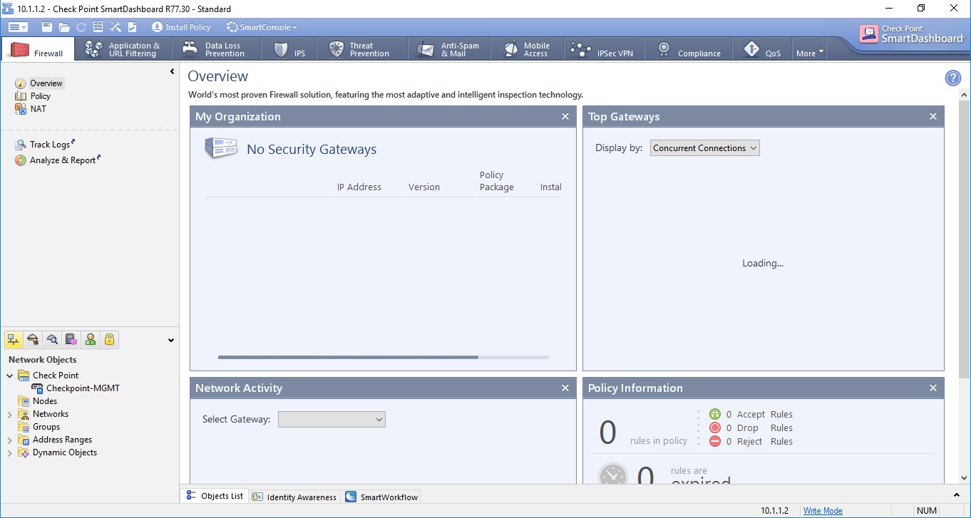
The installation of the “SmartTools” is now complete, using the smartdashboard we are able to access the management server. we use the management server to create policies and configuration we then push these out to “Security Gateways” we now need a Security Gateway to manage.
Deploy the Security Gateway
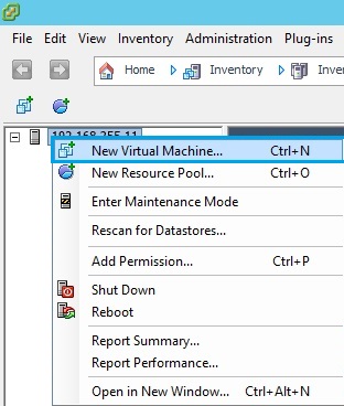
1. From vSphere, right click the host and select “New Virtual Machine”
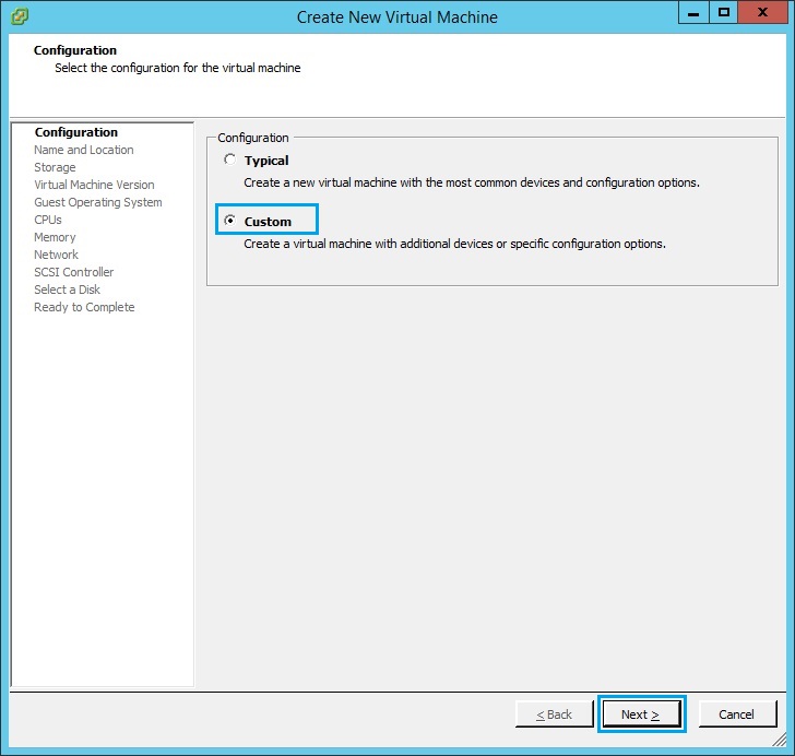
2. Select “Custom” and click “Next”
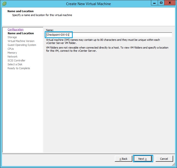
3. Give the VM a name, In this instance its called “Checkpoint-GW-01”
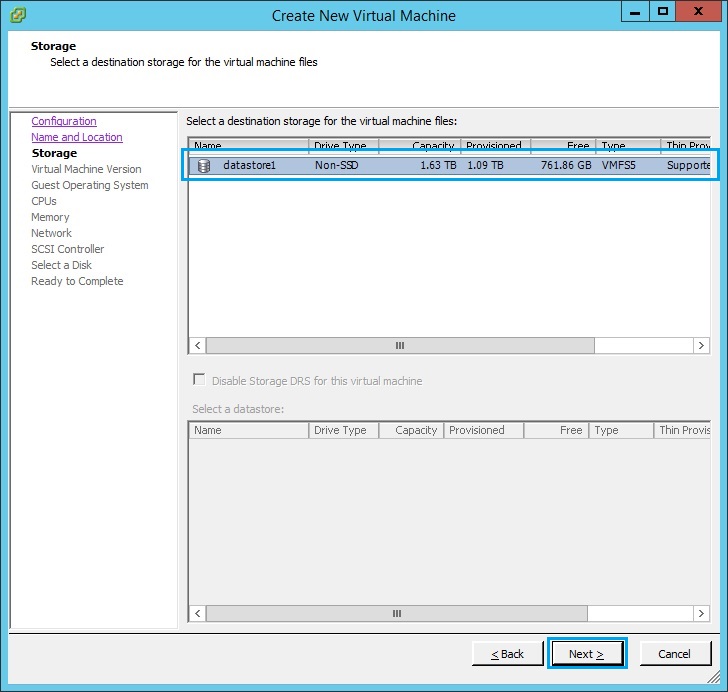
4. Select the data store to store the VM and click “Next”
5. Select “Virtual Machine Version: 11” and click “Next”.
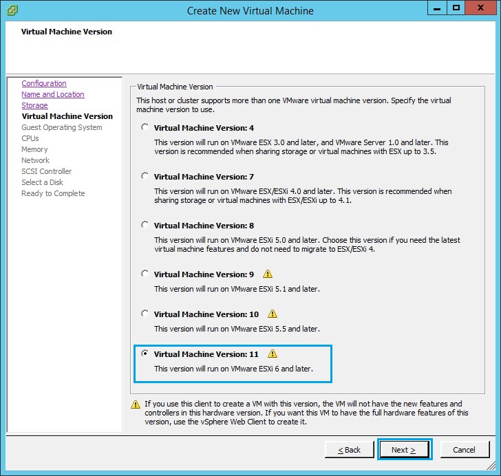
6. Select “Linux” as the guest operating system. From the drop down menu select “Other Linux (32 bit)” as the “Version”
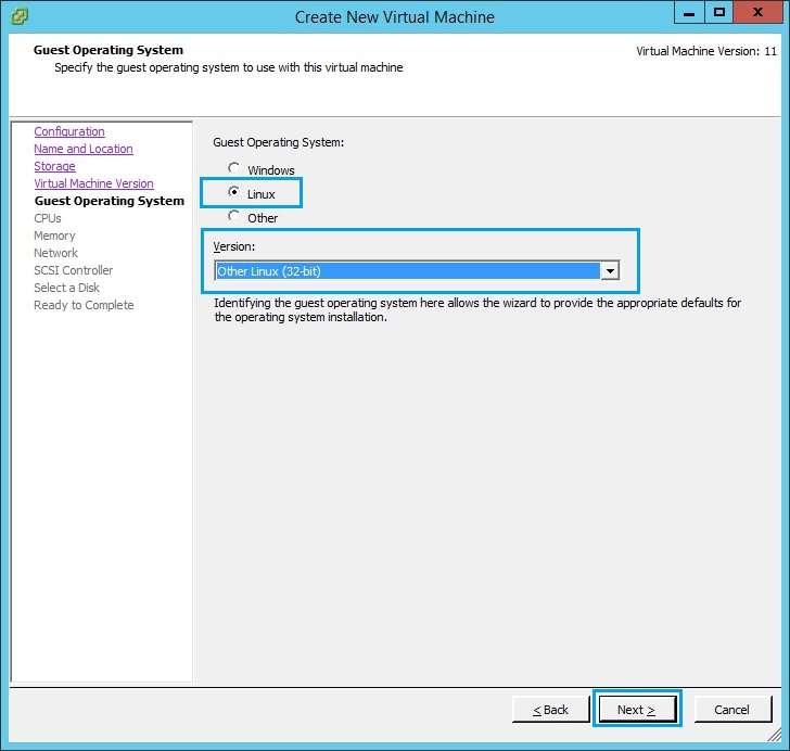
7. Assign the VM CPU according to the hardware capability of the ESX host. In this case i have assigned “2 Virtual sockets” and “2 Cores per socket”. Click “Next”
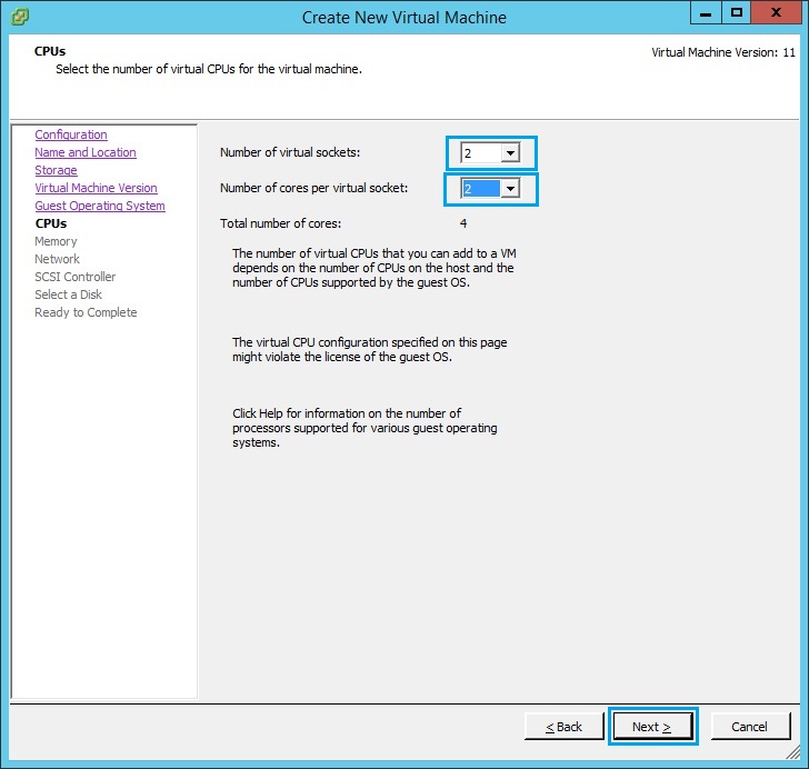
8. Give the VM a minimum of 4GB RAM and click “Next”
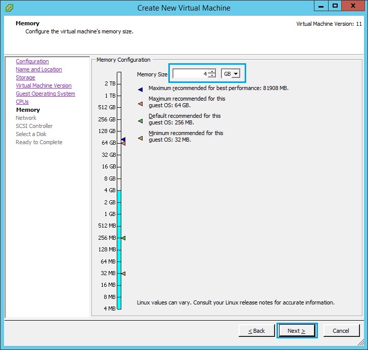
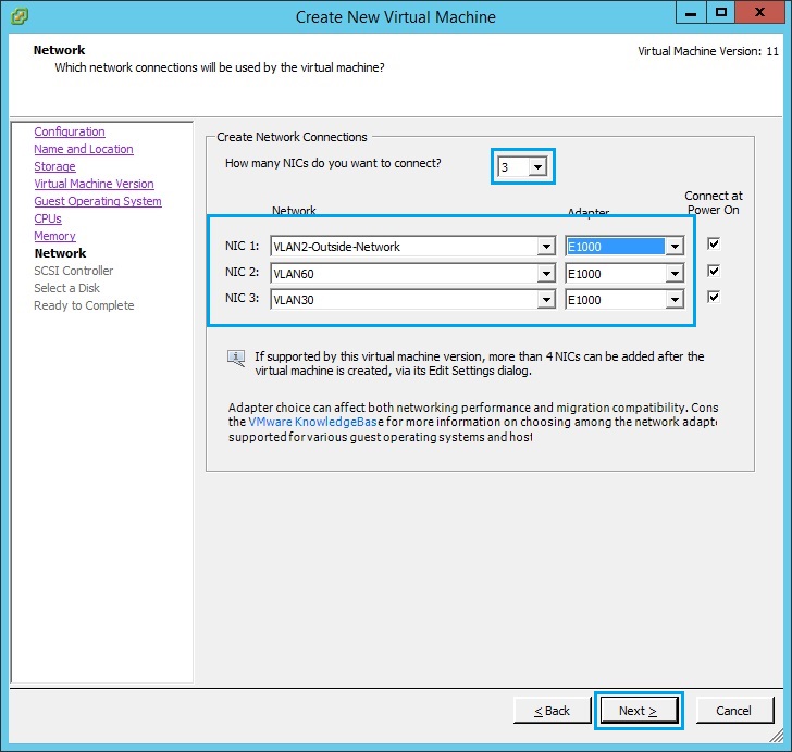
9. Give the “Security Gateway” 3 NIC’s and assign it to the appropriate VLANs. In our case “VLAN2” will be for the outside network, “VLAN60” will be for the inside network and “VLAN30” will be for the DMZ. Click “Next”
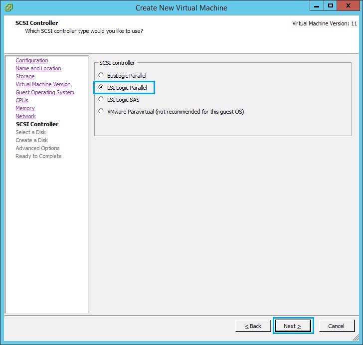
10. Select “LSI Logic Parallel” and click “Next”
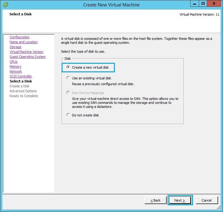
11. Select “Create a new virtual disk” and click “Next”
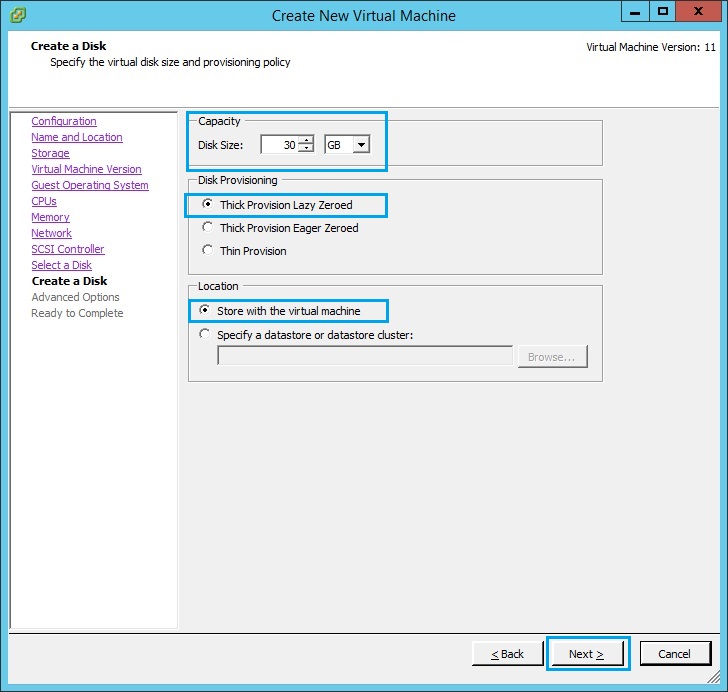
12. Specify the size of the disk in GB, make sure the size is at least “30GB” Select “Thick Provision Lazy Zeroed” and select “Store with virtual machine”Click “Next”
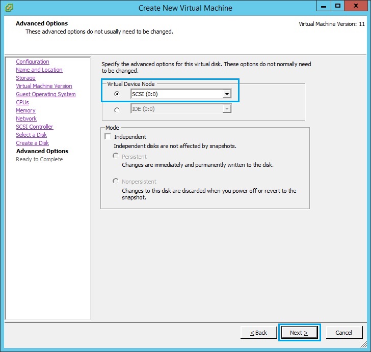
13. Select “SCSI (0:0)” and click “Next”
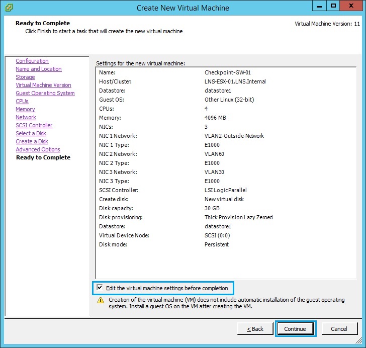
14. At the summary screen, verify all the details are correct, tick “Edit the virtual machine settings before completion” and click “Continue”
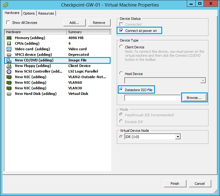
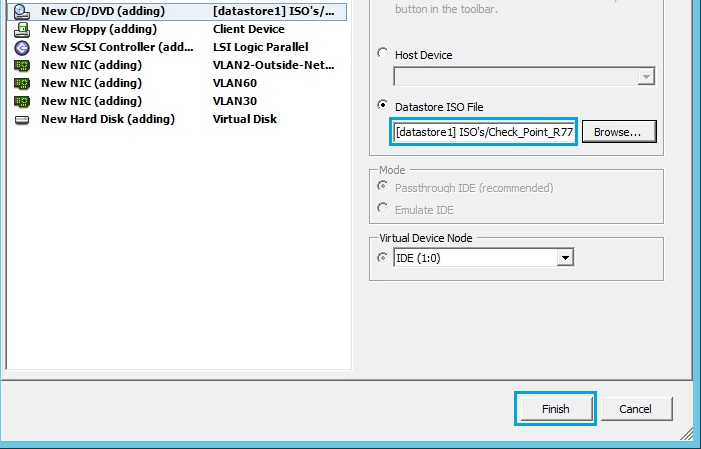
15. From the “Virtual Machine Properties” select “New CD/DVD (adding)”. Tick “Connect at power on” , select “Datastore ISO File”. Click “Browse”
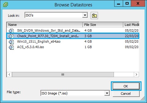
16. Browse the datastore and select the Checkpoint ISO image. Once selected click “OK”
17. The ISO should now be present inside the Datastore ISO File field. Click “Finish”
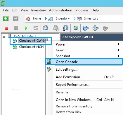
18. Once the VM has been created, right click the VM and select “Open Console”
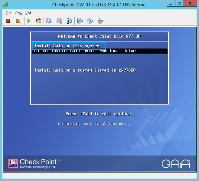
19. Click the green “Play” button to power on the virtual machine. As the VM boots, it will load the specified checkpoint ISO, select “Install GAIA on this system”
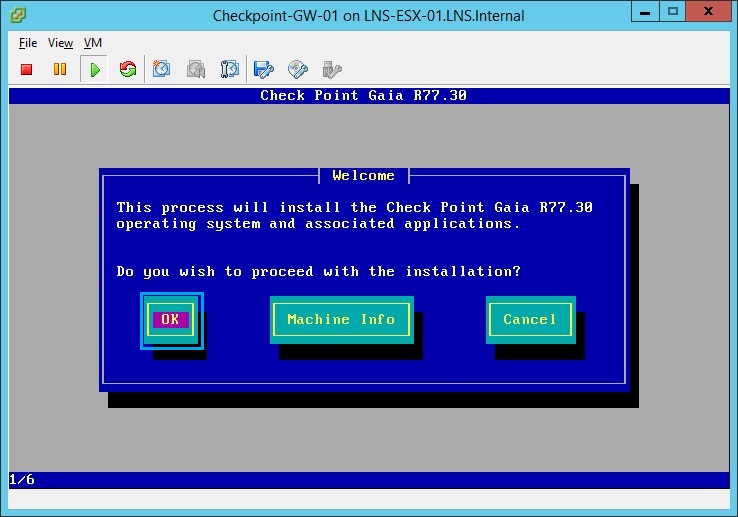
20. At the “Welcome” screen select “OK” to proceed with the install.
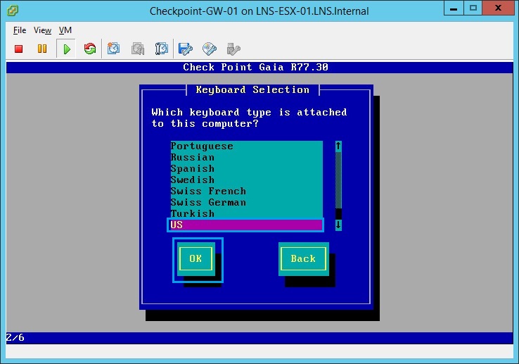
21. Select “US” and click “OK”
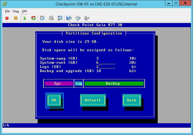
22. Allocate the defaults and select “OK”
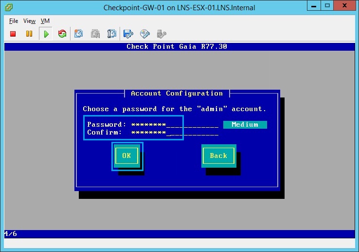
23. Create the “admin” password and click “OK”
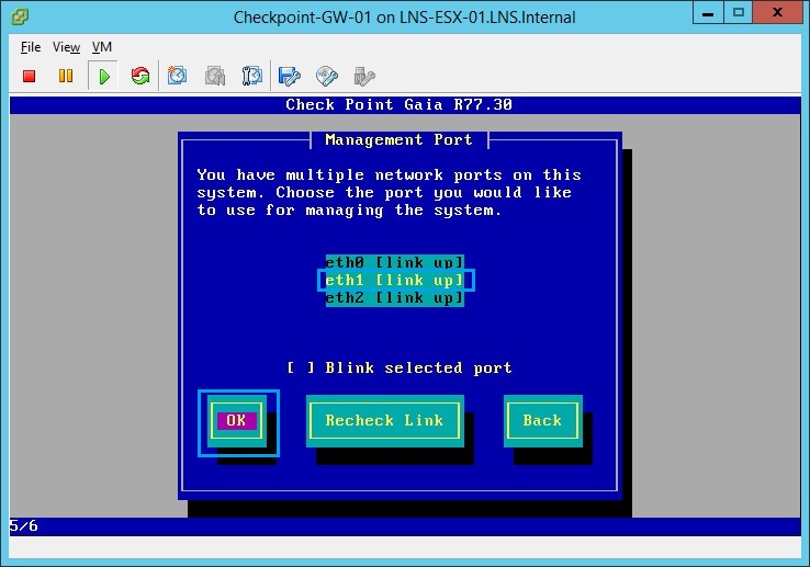
24. From the menu select “eth1”, so that this can be configured as the management IP.
25. The inside network will be “10.1.1.0/24” we will use “10.1.1.1/24” as the IP. We wont specify a default gateway as its not required- later we can add a static default route via the web GUI as the next hop.
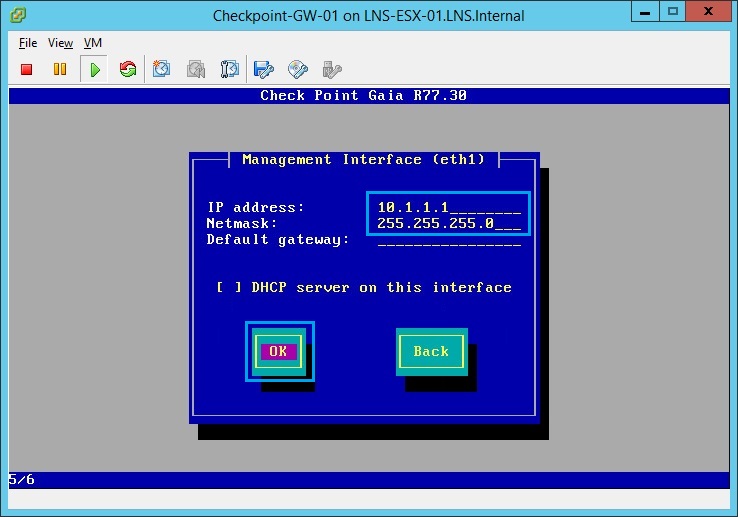
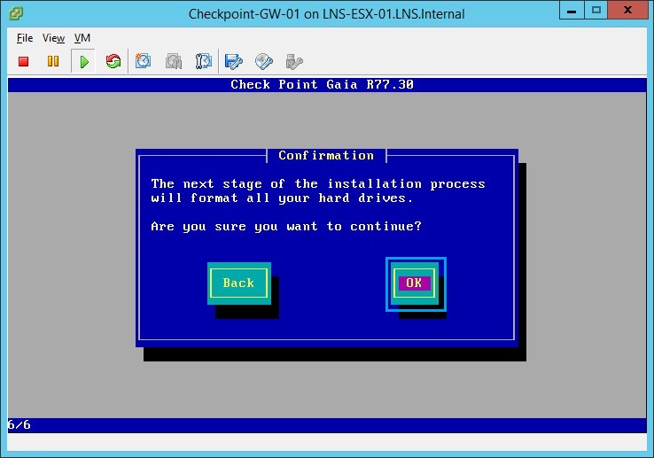
26. At the confirmation screen click “OK”, the device will reformat the HDD and install the GAIA OS.
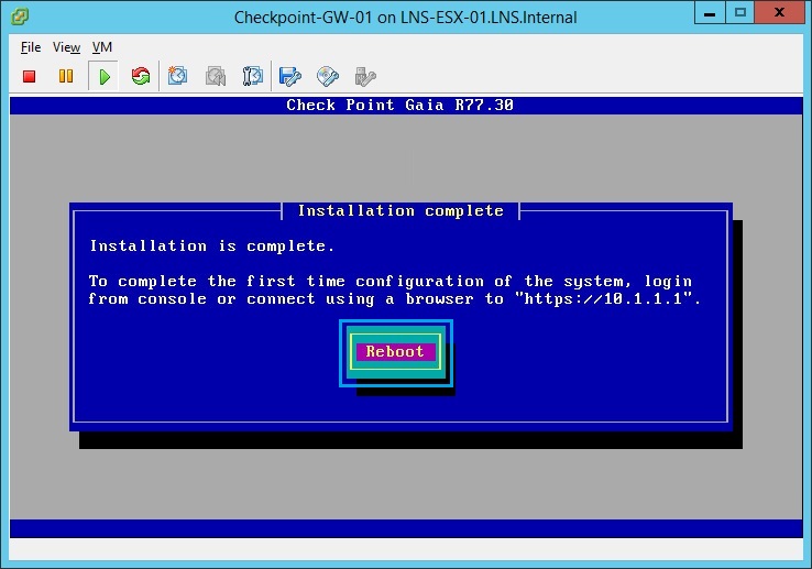
27. Once installation is complete the device will prompt to “Reboot” click “Reboot”
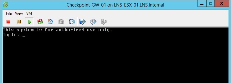
28. Once the system as rebooted and is ready it will display the logon prompt
29. From the workstation launch a browser and navigate to “https://10.1.1.1” at the warning prompt, click “continue to this webpage (not recommended)”
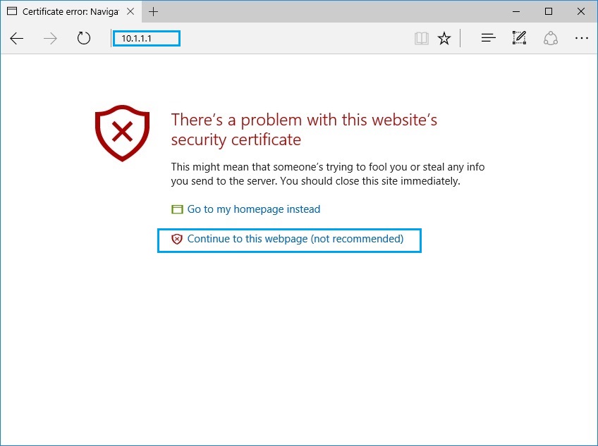
30. At the login prompt for “GAIA” use the username “admin” and the password that was set at the previous step.
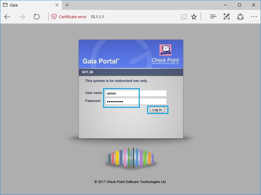
31. Once logged in, the device will display a “First Time Configuration Wizard” to complete the initial setup. At the prompt click “Next”
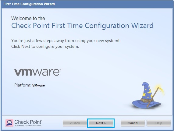
32. Select “Continue with Gaia R77.30 configuration” and click “Next”
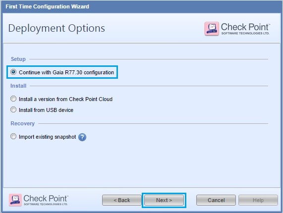
33. Verify the IP address details are correct and click “Next”
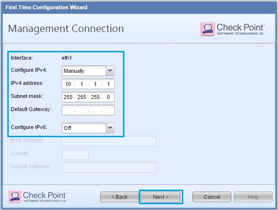
34. leave the settings for “eth0” as default, as we will configure this later via the web GUI. Click “Next”
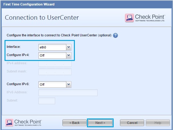
35. Give the device a “Host Name”, “Domain Name” and “DNS server” details. Click “Next”
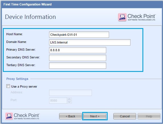
36. Ensure the time setting are correct and click “Next”
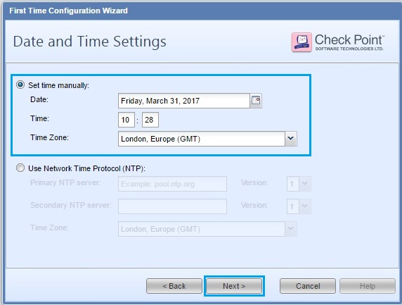
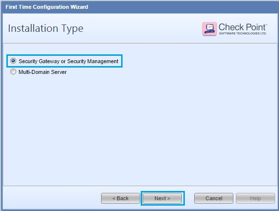
37. Select “Security Gateway or Security Management” Click “Next”
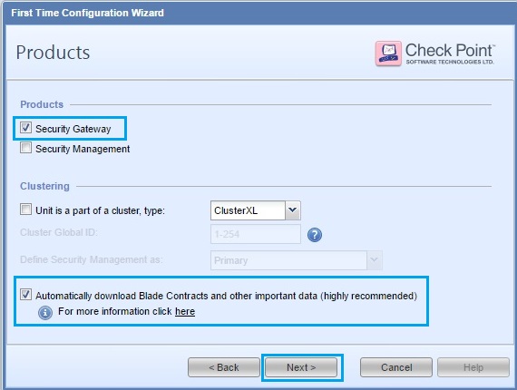
38. From the checkbox option, select “Security Gateway” and check the “Automatically download Blades Contracts and other important data (highly recommened)” box. Click “Next”
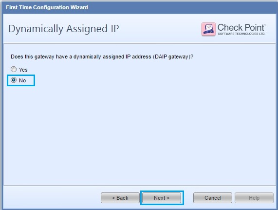
39. Select “No” and click click “Next”
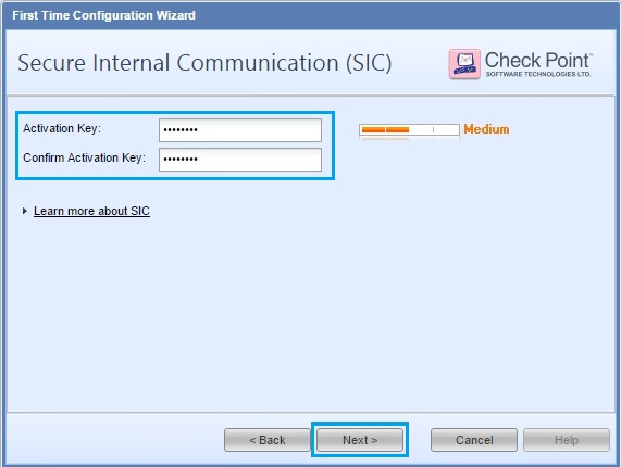
40. Enter a one time password for “SIC” (Secure Internal Communication). This password will be used later when we add the gateway into the “Management Server”.
41. Click “Finish” at the summary screen to begin configuration. This process will take a few minutes to complete.
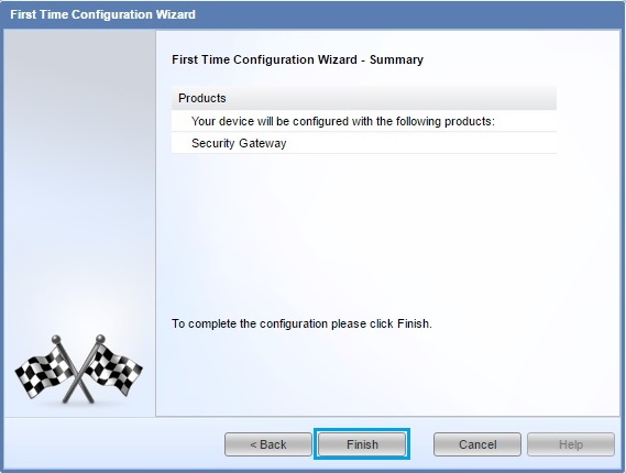
42. Click “Yes” at the prompt.

43. Once the configuration is complete, click “OK” to allow the device to reboot.
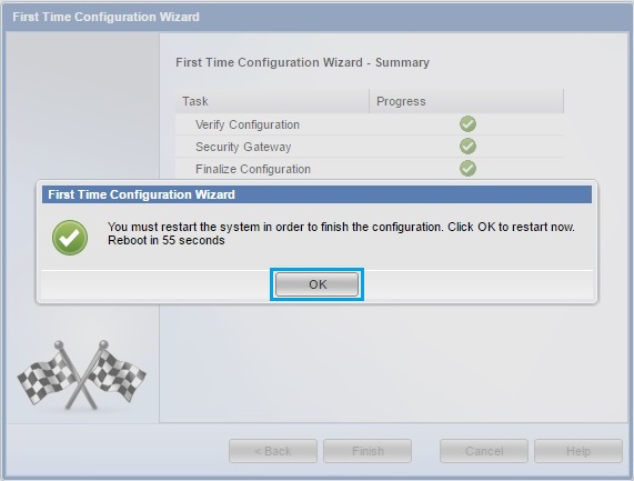
44. The device will reboot, which will take around 2 minutes to complete.

45. Once the device comes back up, from a workstation launch a browser and navigate to “https://10.1.1.1”. Click “Continue to this webpage (not recommended)”
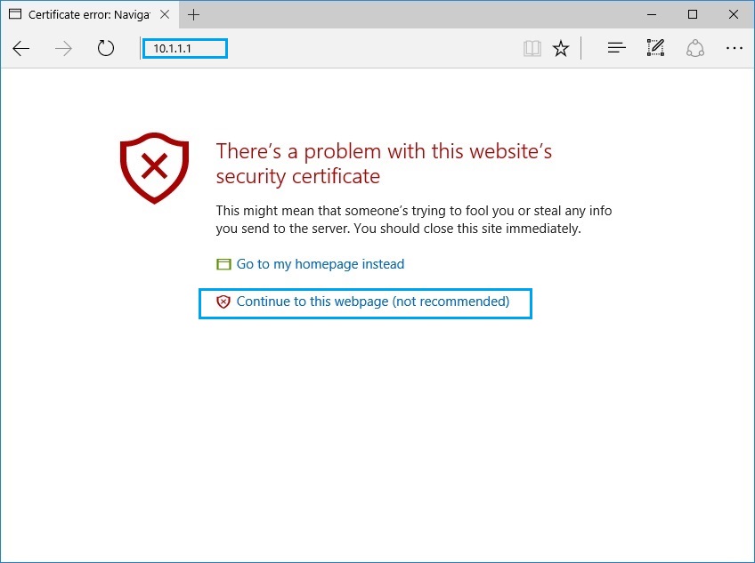
46. At the login prompt for “GAIA” use the username “admin” and the password that was set at the previous step.
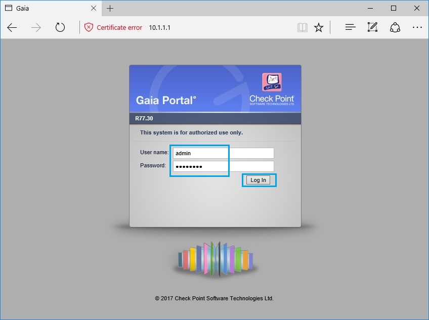
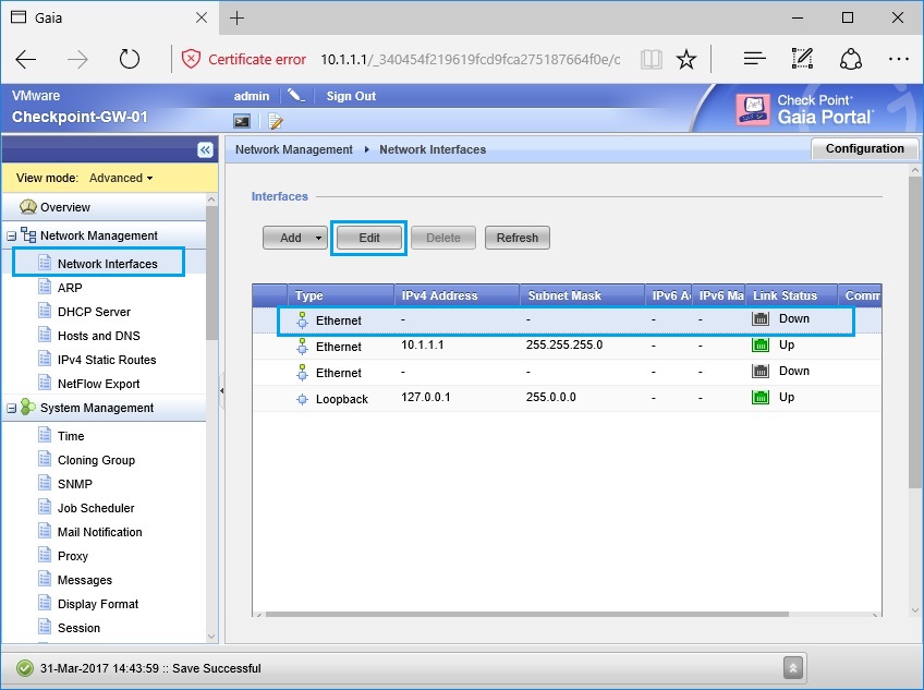
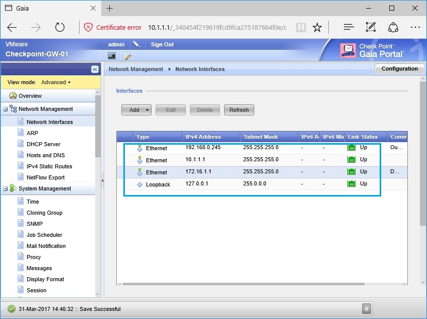
47. Navigate to “Network Interfaces”, highlight “Eth0” and click “Edit”, the status of the interface should be down.
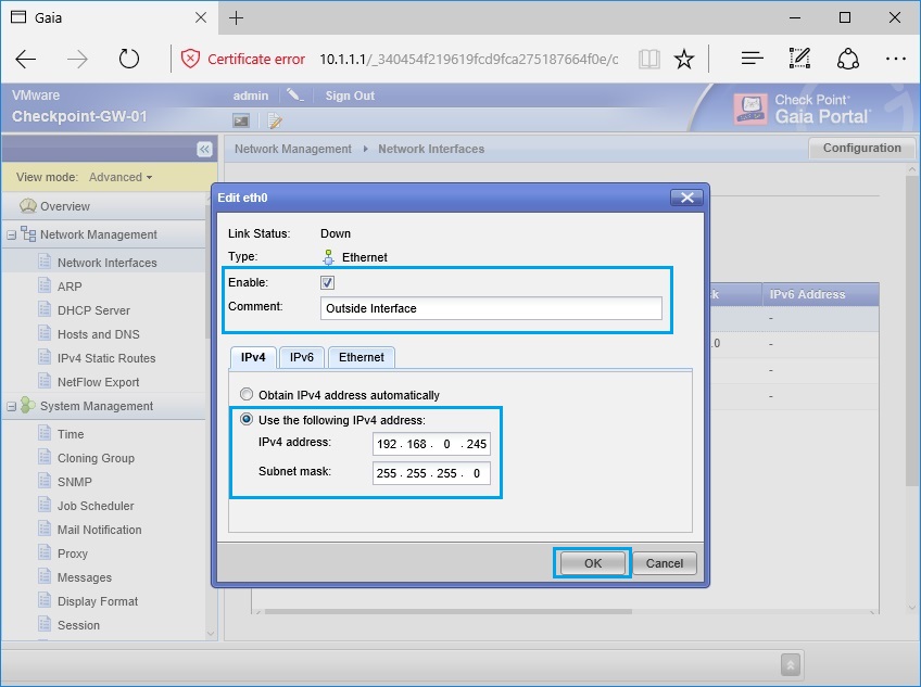
48. Tick “Enable” give the interface the name “Outside Interface” and specify the IP address that will be used on the outside. in this case we will use “192.168.0.245/24”. Click “OK”
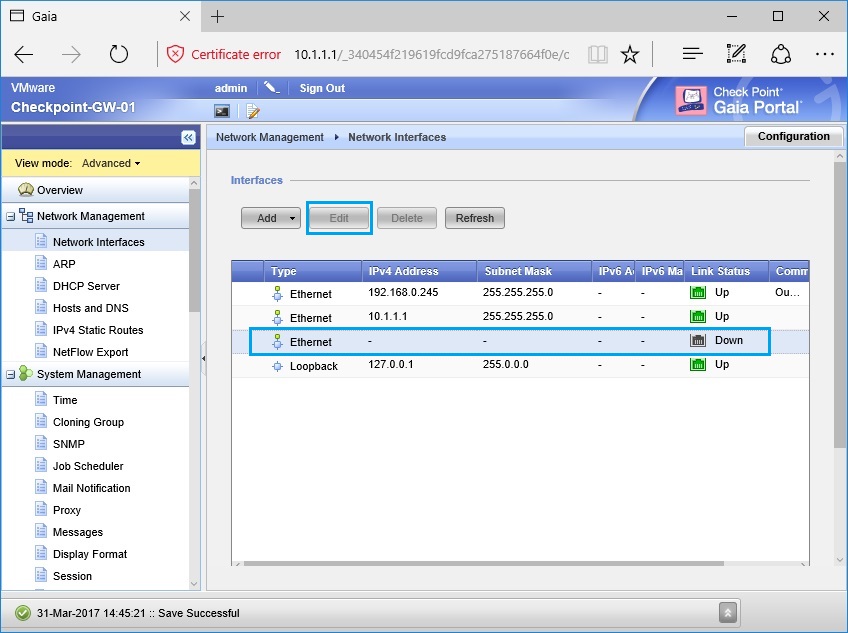
49. Select “Eth2” and click “Edit”.
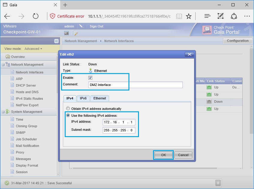
50. Tick “Enable” and give the interface a name. In this instance we will use this as the “DMZ interface”. the IP address will be “172.16.1.1/24”. Click “OK”.
51. The status of all 3 interfaces should now be up. the device will automatically save any changes made in the web GUI.
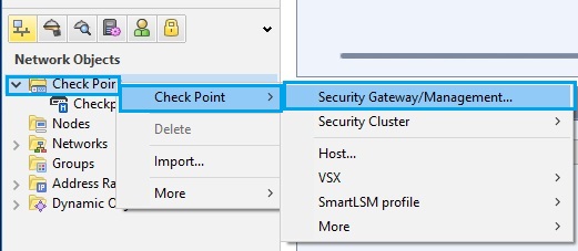
52. Back on the workstation, from “SmartDashboard” right click “Checkpoint” scroll right to “Checkpoint” and click “Security Gateway/Management”
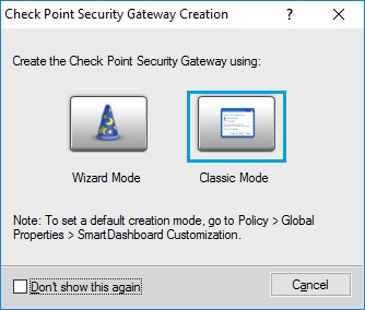
53. From the menu select “Classic Mode”
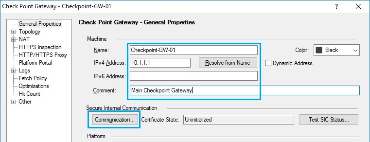
54. The gateway properties window will appear, insert the host name in the “Name” field, and insert the IP address inside “IPv4 Address”. Finally click “Communication”
55. Insert the one time password created earlier and click on “Initialize”
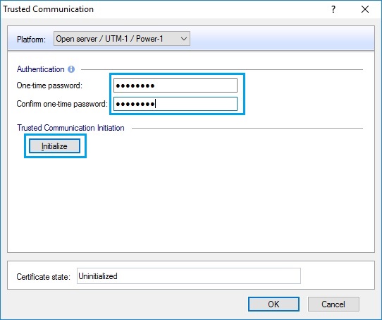
56. Once initialization is complete the page will become grey and a small notice will be displayed as “Trust established”. If you encounter any issues at this stage – the password may need to be reset, use the the following step outlined in this article to complete this. Click “OK”
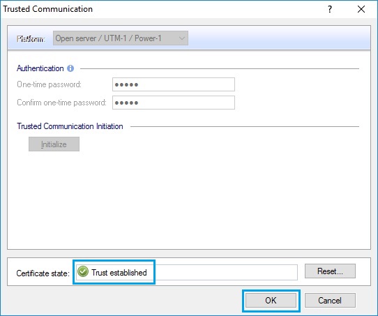
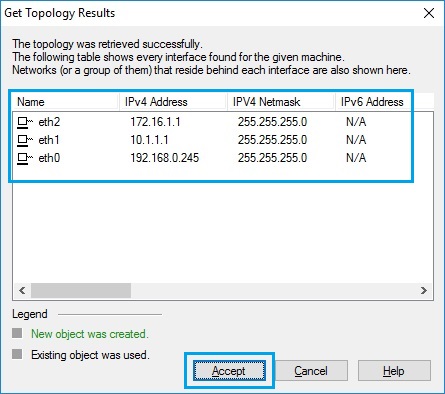
57. A window will appear with all the interfaces of the security gateway to indicate this is what has been discovered when the gateway was added and secure communication was established. Click “Accept”
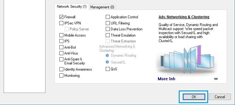
58. Click “OK” to close the gateway properties.
59. From “SmartDashboard” on the top left select “Policy” and click the add new rule icon located at the top center.

60. An empty rule will appear as shown below, for the time being we don’t need to start creating policies, but we can test the installation of the policy by simply using a blank rule and clicking “Install Policy” to ensure it completes successfully. Click “Install Policy”

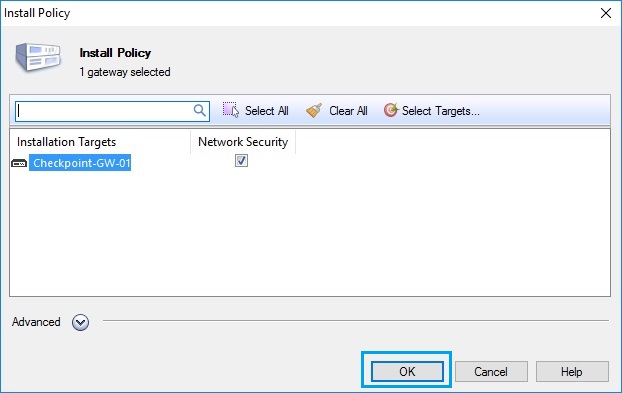
61. At the “Install Policy” window click “OK”
62. the installation of the policy may take a few minutes to complete, and once done it will display a “Installation completed successfully” message. Click “OK” to close the window.
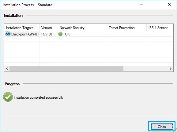
All aspects of the solution is now complete, we have the basics in place from here we can start creating our rule base and NAT policies. The first policy installation has validated that our “Smart Tools”, “Management Server” and “Security Gateway” are all working and have been setup correctly.
