Private VLAN Concept/Implementation
Private VLANs are basically VLANs within a VLAN, they partition a regular VLAN domain into sub-domains. A sub-domain is represented by a “Primary” VLAN and a “Secondary” VLAN, this is called a “VLAN pair”.
You can have multiple VLAN pairs for example one VLAN pair for each sub-domain. All VLAN pairs share the same primary VLAN. The secondary VLAN ID differentiates one sub-domain from another
The Primary VLAN
A private VLAN has only one primary VLAN. Every port in a private VLAN is a member of the primary VLAN. The primary VLAN carries unidirectional traffic downstream from the promiscuous ports to the host ports (isolated and community) and to other promiscuous ports.
Secondary VLAN types
Isolated VLAN – A private VLAN has only one isolated VLAN. An isolated VLAN is a secondary VLAN that carries unidirectional traffic upstream from the hosts toward the promiscuous ports and the gateway. Ports within an isolated VLAN cannot communicate with each other at layer 2
Community VLAN – A community VLAN is a secondary VLAN that carries upstream traffic from the community ports to the promiscuous port gateways and to other host ports in the same community, but cannot communicate with other communities at layer 2. You can configure multiple community VLANs.
Private-VLAN port Types (access ports)
Promiscuous port – A promiscuous port belongs to the primary VLAN and can communicate with all ports, including the community and isolated host ports that belong to the secondary VLANs
Isolated port – An isolated port is a host port that belongs to an isolated secondary VLAN. It has complete Layer 2 separation from other ports within the same private VLAN, except for the promiscuous ports.
Community port – A community port is a host port that belongs to a community secondary VLAN. Community ports can communicate with other ports in the same community VLAN and with promiscuous ports. These ports are isolated at Layer 2 from all other ports in other communities and from isolated ports.
All members in the private VLAN share a common address space, which is allocated to the primary VLAN. Hosts are connected to secondary VLANs, and the DHCP server assigns IP addresses from the block of addresses allocated to the primary VLAN
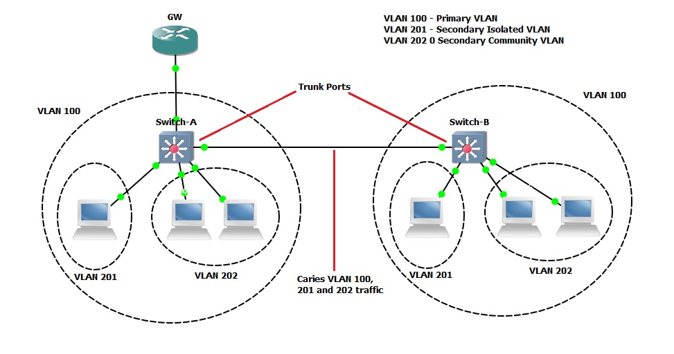
As with regular VLANs, private VLANs can span multiple switches. A trunk port carries the primary VLAN and secondary VLANs to a neighbouring switch. The trunk port treats the private VLAN as any other VLAN.
For example – If we are trunking an Isolated VLAN across multiple switches the feature of private VLANs will not allow the traffic from “Switch-A” to reach an isolated port on “Switch B”. However if a community VLAN is stretched the traffic will traverse to switch B
Because VTP versions 1 & 2 do not support private VLANs, you must turn off VTP and manually configure private VLANs on all switches. It is also recommended by Cisco to use the default Switch SDM template to balance system resources between unicast routes and Layer 2 entries.
In a Layer 3 switch, an SVI represents the Layer 3 interface of a VLAN. Layer 3 devices communicate with a private VLAN only through the primary VLAN and not through secondary VLANs. You would only configure Layer 3 VLAN interfaces only for primary VLANs. You cannot configure Layer 3 VLAN interfaces for secondary VLANs. SVIs for secondary VLANs are inactive while the VLAN is configured as a secondary VLAN.
Configuration Example:
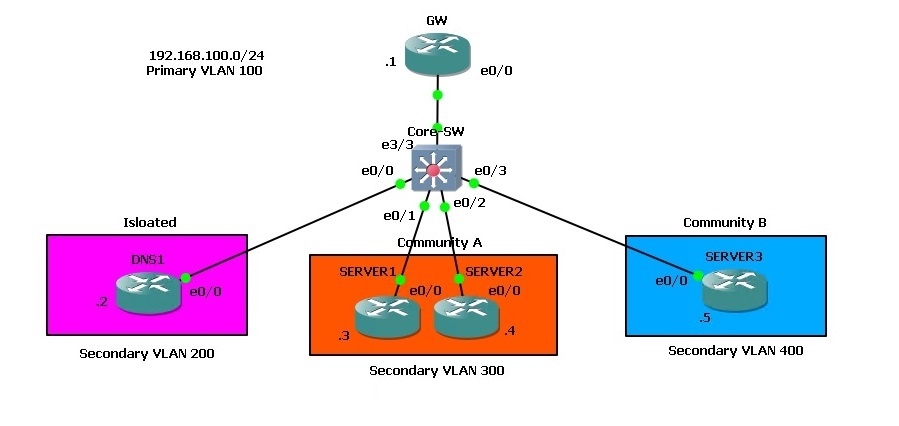
In this step by step guide we will configure Private VLANs to demonstrate how they behave, the topology below was setup using GNS3, and all the devices are IOU devices that are acting as the roles specified. In order to carry out this lab in GNS3, the L2 IOU image must be at least “i86bi-linux-l2-adventerprisek9-15.2d.bin” otherwise Private VLAN port types won’t be recognised.
Basic network connectivity has been setup using the “192.168.100.0/24” Subnet
Lets get started!
Step 1. Check the current state of private VLANs to ensure nothing is present, we can see from the output below that private VLANs currently do not exist on this device.
#show vlan private-vlan

Step 2. On the switch disable VTP and setup the “Community” and “Isolated” VLANs, these will all be “Secondary” VLANs
#conf t
#vtp mode transparent
#vlan 400
#private-vlan community
#vlan 300
#private-vlan community
#Vlan 200
#private-vlan isolated

Step 3. Configure the “Primary” VLAN and associate all the “Secondary” VLANs to the “Primary”
#conf t
#vlan 100
#private-vlan primary
#private-vlan association 200,300,400

Step 4. looking at the configuration, we can see that the switch now knows which VLAN is the “Primary” and which VLANs are “Secondary”, the switch also knows whether the ports are going to act as a “Community” or an “Isolated” port.
#show vlan private-vlan

Step 5. Create the “Promiscuous port” and assign it to interface “e3/3”, we also need to create the mappings of the “Primary” and “Secondary” VLANs so that the promiscuous port can allow the traffic through.
#conf t
#int e3/3
#switchport mode private-vlan promiscuous
#switchport private-vlan mapping 100 200,300,400
#no shut

Step 6. Now we need to create the association for the “Secondary” VLANs to the “Primary” VLAN on each individual interfaces.
“int e0/0” is going to be used for the “Secondary” VLAN 200 (this will be an Isolated port)
#conf t
#int e0/0
#switchport mode private-vlan host
#switchport private-vlan host-association 100 200

“int e0/1” and “inte0/2” are going to be used for the “Secondary” VLAN 300 (these will both be a Community port for Community A)
#int e0/1
#switchport mode private-vlan host
#switchport private-vlan host-association 100 300
#int e0/2
#switchport mode private-vlan host
#switchport private-vlan host-association 100 300

“int e0/3” is going to be used for the “Secondary” VLAN 300 (this will be Community port for Community B)
#int e0/3
#switchport mode private-vlan host
#switchport private-vlan host-association 100 400

Step 7. Verify the configuration, we should now see the ports assigned to the relevant “Secondary” VLANs and port types.
#show vlan private-vlan

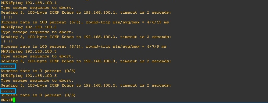
If we test the connectivity using ping we can validate our configuration is working correctly, From “DNS1” ping everything in the topology and see how it behaves. “DNS1” is in the “Isolated” VLAN 200 so it should only be able to communicate with the “Promiscuous” port and nothing else.
From the output below we can see the following –
We can reach .1 which is the GW out the “Promiscuous” port, we can also ping our self which is .2, but we cannot ping any devices in “Community A (VLAN 300)” or “Community B (VLAN 400)”
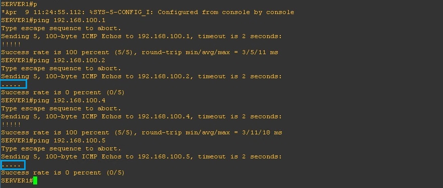
From “SERVER1” repeat the above and ping everything in the topology, from this device we should only be able to reach the “Promiscuous” port and “SERVER2” which is in the same “Community” as “SERVER1”
As we can see below, we can’t reach “DNS1”which is located on the “Isolated” VLAN200 or “SERVER3” on “Community B” inside the “Secondary” VLAN 400
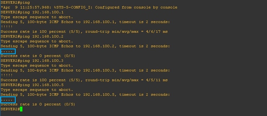
From “SERVER2” repeat the above and ping everything in the topology, from this device we should only be able to reach the “Promiscuous” port “SERVER1” which is in the same “Community” as “SERVER2”
As we can see below, we can’t reach “DNS1”which is located on the “Isolated” VLAN200 or “SERVER3” on “Community B” inside the “Secondary” VLAN 400
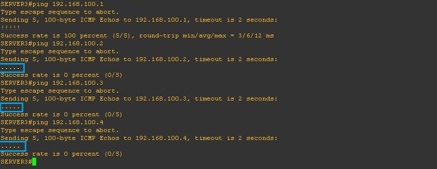
From “SERVER3” repeat the above and ping everything in the topology, from this device we should only be able to reach the “Promiscuous” port
As we can see below, we can’t reach “DNS1”which is located on the “Isolated” VLAN200 or “SERVER1/2” on “Community A” inside the “Secondary” VLAN 300.
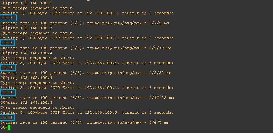
From “Promiscuous” port (GW) repeat the above and ping everything in the topology, from this device we should be able to reach all the devices
