BPDU Guard Concept, STP Attack and Mitigation Example
BPDU Guard, BPDU Filter, Root Guard and Loop Guard are all considered spanning tree security features, they all have different characteristics as to what they protect and how they work. Spanning tree attacks can harm the data-plane at Layer 2 therefore using spanning tree security we can mitigate “Man in the Middle” type attacks, protect against changes in the spanning tree topology, protect the “Root Bridge” and prevent overall network loops.
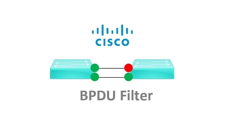
Spanning tree BPDU Guard is used to protect access switches from the user community, BPDU Guard will help prevent an unknown device from participating in Spanning Tree and essentially overruling the root bridge thus preventing a STP topology change.
Out of the box Cisco switches use the original 802.1d Spanning Tree Protocol, which was designed to prevent loops in a network. Switches send BPDU (Bridge Protocol Data Unit) probes into the network every two seconds to discover loops, BPDU frames are also used to help elect the “Root Bridge” the root bridge is normally the “Core” switch that all the other switches forward frames through.
The Root Bridge selection is made according to the device that has the lowest “Bridge-ID” the Bridge ID is made up of two things –
The Bridge Priority- every switch is 32769 by default (can be set higher or lower) lower wins!
The switch’s MAC address – older/lower (manufactured date/numerical/alphabetical) MAC address wins!
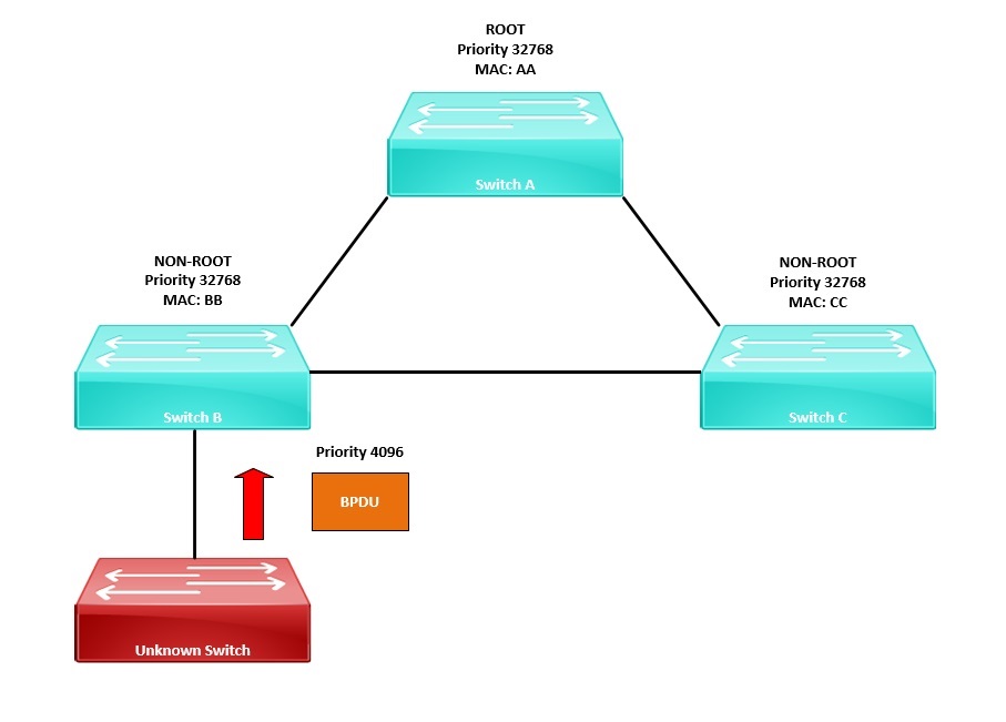
If a user connects an unknown switch into the network, the switch could potentially have a lower “Bridge-ID” that would cause a STP topology change, making the unknown device the new root bridge. All the other switches would then find the best path to the elected root bridge and forward all their traffic via this device. This would be an example of someone accidently causing the STP topology to change, which would severely impact the performance of the network.
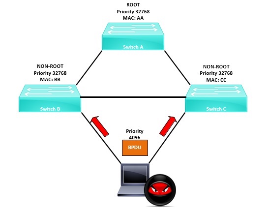
Alternatively, a malicious user with some software could connect themselves onto two switches, send superior BPDU frames and cause the STP topology to change. The malicious user would then become the root bridge and using Wireshark they could capture traffic as it goes through them.
BPDU Guard says, if I see BPDU’s come in on a protected port, I will immediately disable that port and place it into an “err-disabled” state.
It is Cisco’s best practice that BPDU Guard should be enabled on all ports connecting to the user community. BPDU Guard can be enabled globally or on specific switch ports.
Attack Example:
Warning: do not carry out anything outlined in this guide on a live network, and always ensure you have the relevant permissions if you are testing this out for yourself, this should only be done in a lab environment or test network. This document is for the purpose of understanding how these attacks work and how to mitigate against them.
In the example below, we will take a look at sending in BPDU frames into the network to manipulate the Spanning Tree topology and make the attacker’s machine the “Root Bridge” the topology has been setup in “GNS3” with “Kali-Linux” acting as the attacking machine. For simplicity we will use a single VLAN (VLAN1), basic networking is in place.
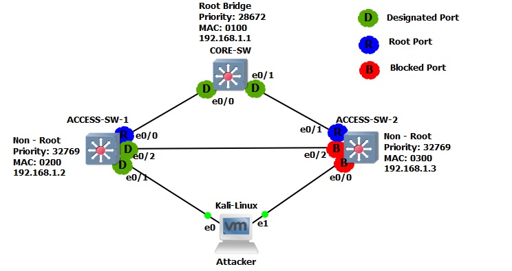
Let’s get started!
Step 1. Let’s take a look at the current STP topology on all the devices,
CORE-SW
#show spanning-tree
From the output below we can see that “Rapid Spanning Tree” is running on the switch for VLAN 1. The device is acting as the “Root Bridge” and its priority is “28673”. We can also see that all the ports are in a “Designated” state, this is normal behaviour for all ports on the root.
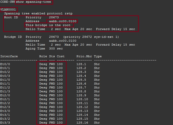
ACCESS-SW-1
#show spanning-tree
From the output we can see that the device is participating in “Rapid Spanning Tree” for VLAN 1, the “Root Bridge” is the device with MAC “aabb.cc00.0100” (which is the CORE-SW). The device itself has the priority of “32769” and its MAC address is “aabb.cc00.0200”. The device has also lit up a “Root” port which is “E0/0” this port has the best path to the root bridge.
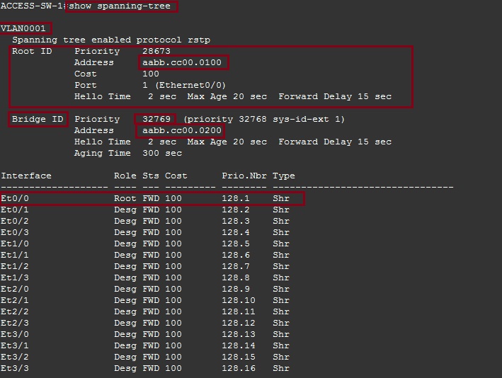
ACCESS-SW-2
#show spanning-tree
From the output below we can see that this switch also running “Rapid Spanning Tree” for VLAN 1, the “Root Bridge” is the device with MAC “aabb.cc00.0100” (which is the CORE-SW). The device itself has the priority of “32769” and its MAC address is “aabb.cc00.0300”. The device has also lit up a “Root” port which is “E0/1” this port has the best path to the root bridge. The device is also blocking two redundant ports, “E0/0” and “E0/2” in order to prevent a loop.
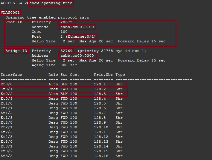
If the attack is successful we should see the attacker’s machine become the “Root Bridge” as the BPDU sent by this device will have a lower “Bridge-ID” than that of the “CORE-SW”. We should also see blocked port “E0/0” on “ACCESS-SW-2” change its state and become a “Root” port as its path to the “Root Bridge”.
Step 2. Let’s setup debugging on all three switches so that we can see what happens when the attack is carried out.
CORE-SW
#debug spanning-tree config
#debug spanning-tree events
#debug spanning-tree bpdu receive
#debug spanning-tree general
#debug spanning-tree root

ACCESS-SW-1
#debug spanning-tree config
#debug spanning-tree events
#debug spanning-tree bpdu receive
#debug spanning-tree general
#debug spanning-tree root

ACCESS-SW-2
#debug spanning-tree config
#debug spanning-tree events
#debug spanning-tree bpdu receive
#debug spanning-tree general
#debug spanning-tree root

Step 3. From the “Kali Linux” machine launch an attack using “Yersinia” to send superior BPDU’s into the network.
#yersinia –I
![]()
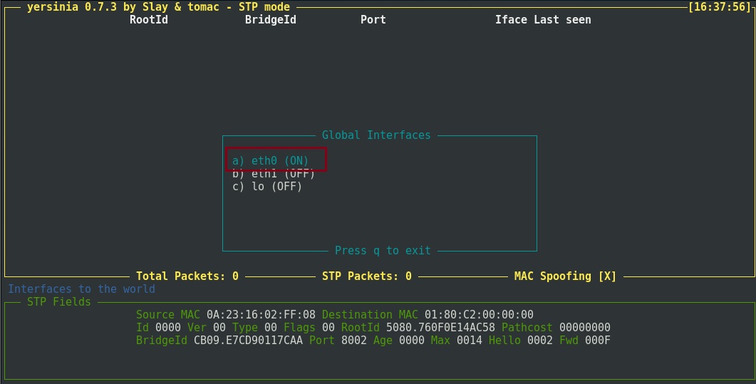
Step 4. Press “I” to select the interface to use for the attack, highlight “eth0” ensure it is set as “On” and press “q” to exit
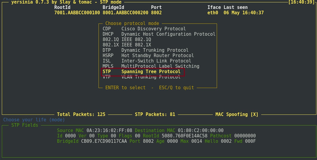
Step 5. Hit the “g” key to load the attack type, select “STP” and hit “enter”
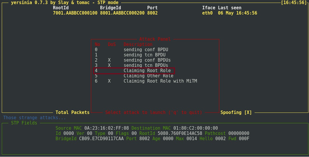
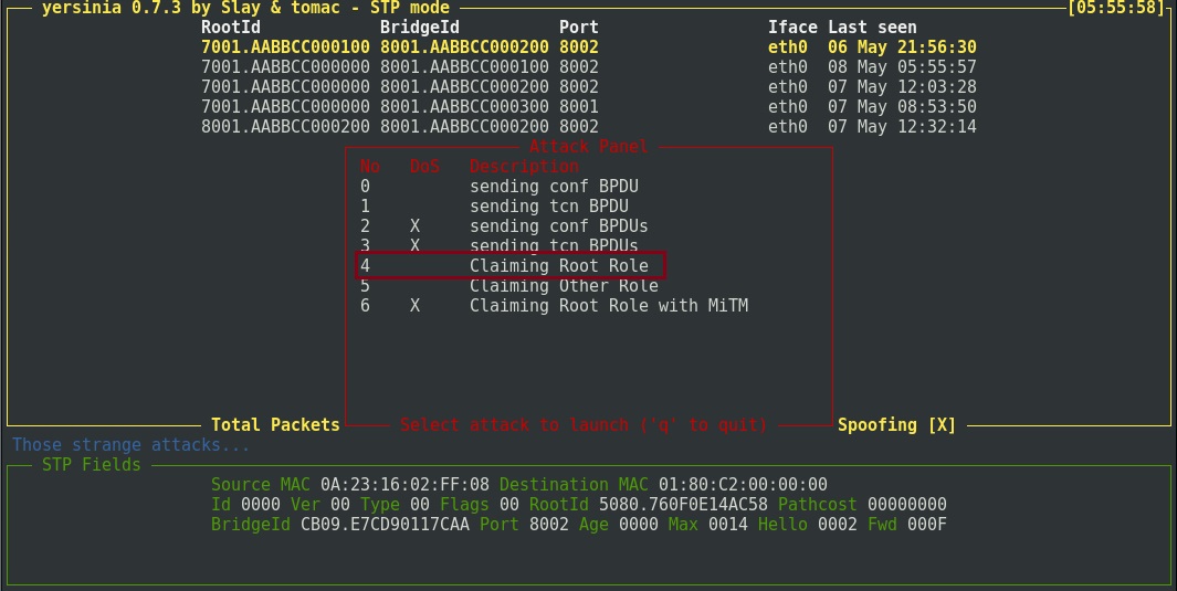
Step 6. Hit the “x” key to select the attack type and press “4” to “Claiming Root Role” to run the attack.
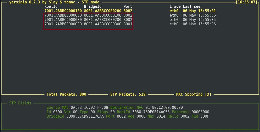
Yersinia will now send BPDU’s into the network first establishing who the “Root Bridge” is and then claiming to have a lower “Bridge-ID” than the real “Root Bridge”. The MAC address the kali box will use is shown below in the “Bridge-ID”. This is “AABB.CC00.0000”
Step 7. Let’s take a look at the damage by reviewing the debug messages on all three switches.
CORE-SW
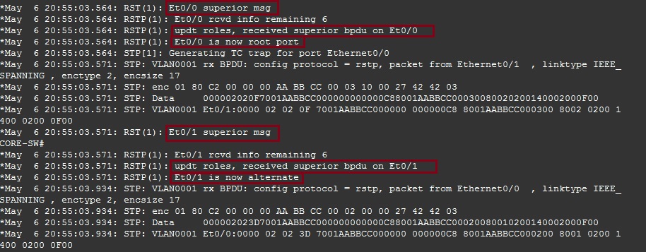
From the output below we can see that “CORE-SW” received a superior BPDU on “E0/0” therefore it updated its role and changed its state from “Designated” to “Root”. The device also received a superior BPDU on “E0/1” and therefore updated its role and changed its port state from “Designated” to “Alternate” (Blocked).
ACCESS-SW-1
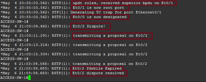
“ACCESS-SW-1” received a superior BPDU on “E0/1” claiming there is a new “Root Bridge” therefore it updated its role and changed its state from “Designated” to “Root”. The device also received a superior BPDU on “E0/2” and began a dispute as to which port to block. As “ACCESS-SW-1” has the same “Priority” as “ACCESS-SW-2” the device with the lower MAC address will win and the other side will be blocked. In this case MAC “0200” is lower than “0300” therefore “ACCESS-SW-1” wins the dispute and resolves it. Interface “E0/2” remains as a “Designated” port.
ACCESS-SW-2
“ACCESS-SW-2” receives a superior BPDU on “E0/0” which is a blocked port, the device now must find the best path to the “Root Bridge” and therefore changes its role from “Blocked” to “Root” for “E0/0”. As we saw earlier on “ACCESS-SW-1” a dispute took place as to which side of the redundant link to block, “ACCESS-SW-1” won the dispute and interface “E0/2” on “ACCESS-SW-2” was blocked, we can see this below, “Et0/2” is now blocking. Interface “E0/1” will change its role from “Root” to “Designated” as the other side of the link on “CORE-SW” is being blocked.

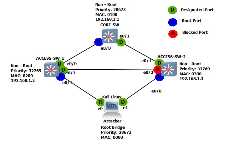
The Spanning tree topology has changed and now looks like this:
Step 8. If we take a look at the Spanning Tree configuration we can verify the changes as we have seen in the debug messages.
CORE-SW
#show spanning-tree
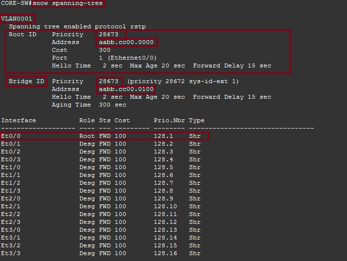
The “Root-Bridge” has a priority of “28673” and the following MAC address “aabb.cc00.0000” the “CORE-SW” has a priority is “28673” and its MAC address is “aabb.cc00.0100”. Although the “Priority” for both devices match, we can see that the MAC address of the newly elected root is lower therefore it won the election and became the root. The “CORE-SW” has also lit up “E0/0” as its root port as we have seen in the debug messages.
ACCESS-SW-1
#show spanning-tree
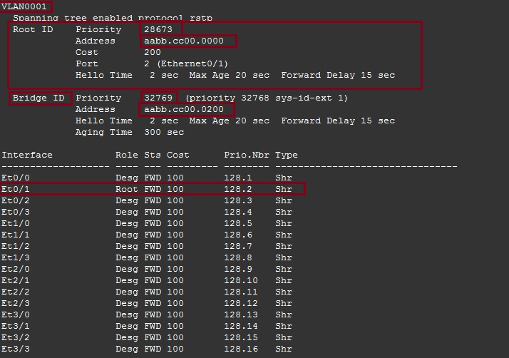
On “ACCESS-SW-1” we can see that the device knows the newly elected “Root Bridge” and has identified it with its priority of “28673” and it MAC address of “aabb.cc00.0000” the devices has elected “E0/1” as its root port.
ACCESS-SW-2
#show spanning-tree
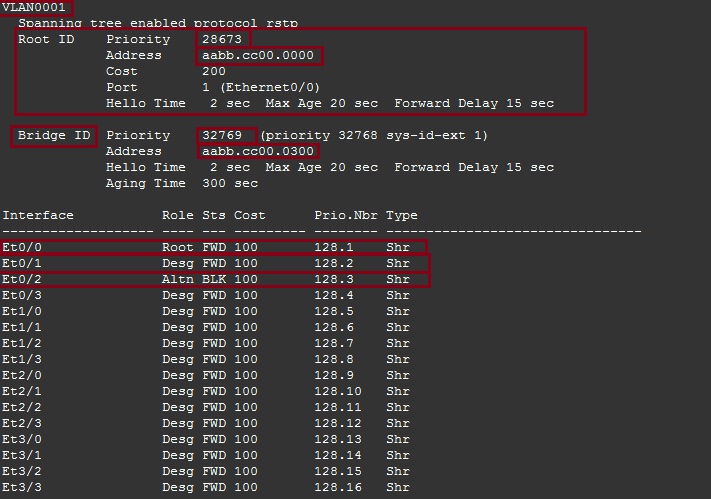
On “ACCESS-SW-2” we can see that this device also knows the newly elected “Root Bridge” and has identified it with its priority of “28673” and it MAC address of “aabb.cc00.0000” the devices has elected “E0/0” as its root port, and blocked the redundant link on “E0/2”
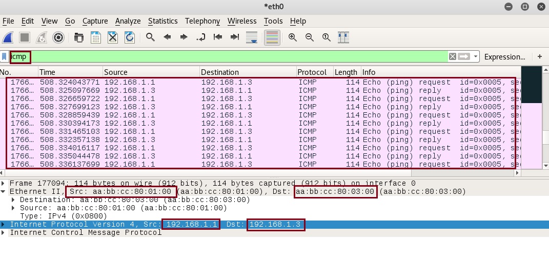
Step 9. Using Wireshark we can now capture traffic as it passes the “Kali-Linux” machine, as a test let’s see if we can see ICMP traffic as we ping “ACCESS-SW-2” from the “CORE-SW”. The traffic should go from the “CORE-SW” to “ACCESS-SW-1” through the “Root” (which is the Kali-Linux) and to “ACCESS-SW-2”
On the Kali-box Launch Wireshark and begin a capture.
#Wireshark
![]()
From “CORE-SW” ping “ACCESS-SW-2”
#ping 192.168.1.3 repeat 10

from the Wireshark capture we can see the ICMP packets going from source “192.168.1.1” to destination “192.168.1.3” we can also see the source and destination Layer 2 address. If we were transmitting data, we would be able to sniff the traffic and rebuild the packets.
Let’s protect against this using BPDU Guard
Global Configuration Example
Step 1. enable BPDU Guard in global configuration mode.
ACCESS-SW-1
#conf t
#spanning-tree portfast bpduguard default

ACCESS-SW-2
#conf t
#spanning-tree portfast bpduguard default

Step 2. Configure all the access ports that connect back to the user community as “Portfast” (do not configure any trunk ports or ports that connect to other switches as portfast as they will need to listen out for BPDU’s, also there is risk of causing a loop if switches can’t see BPDU probes).
ACCESS-SW-1
In our case we can just configure “E0/1” as “Portfast” for “ACCESS-SW-1” since this is our only access port. However, you may want to configure this using the range command for all you access ports.
#int e0/1
#spanning-tree portfast
As we can see the command does come with a warning recommending not to configure portfast on a port that connects back to a switch or hub.

ACCESS-SW-2
Again we can just configure “E0/0” as portfast for “ACCESS-SW-2” since this is our only access port.
#int e0/0
#spanning-tree portfast

Step 3. From the Kali-Linux machine lets send some BPDU’s and attempt to introduce the new “Root”
On “Yersinia” Press “x” to launch the attack and select option “4”
ACCESS-SW-1
Instantly after enabling BPDU Guard we can see that BPDU’s were blocked for interface “E0/1” coming in from our attacking machine. The port has now been shut down and placed in to “err-disabled” state. If we want to bring the interface back up, we need to do a “shut” and “no shut”.

#show interface status errdisabled

ACCESS-SW-2
Again we can see that BPDU’s were blocked on interface “E0/0” and the interface was shutdown.

#show interface status err-disabled

Port by Port Configuration
Step 1. Enter the configuration mode for the interfaces you wish to configure “BPGU Guard” on and enter the following:
#conf t
#interface e0/0
#spanning-tree portfast
#spanning-tree bpduguard enable
It is ideal to use the range command for multiple ports.

