Loop Guard Concept and Implementation
Loop Guard and UDLD (Uni-directional Link Detection) are two ways to protect networks against loops. Loop guard is a spanning-tree optimisation protocol and can work with both Fibre and UTP cables while UDLD only works with fibre and is a layer 1/2 protocol (unrelated to spanning-tree) that protects the upper layer protocols from causing loops.
Loop Guard is generally used to protect against a mal-functioned switch. For example, in a normal STP state – the Root would send BPDU’s into the network every two seconds to discover loops. If a loop is discovered the switch with the highest “Bridge-ID” would block one if its links to prevent the loop, however it will continue to send and receive for BPDUs on that port.
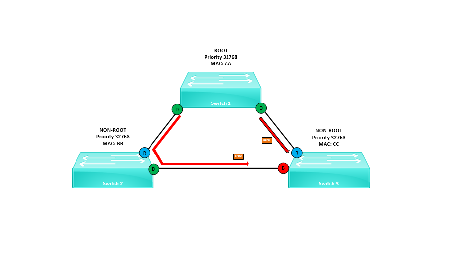 If for any reason BPDU’s stop coming in on that blocked port from the neighbour device the switch will assume there is no longer a switch attached to that port and transitions the port into a forwarding (Designated) state. This has now caused a loop on the network.
In reality the switch is still connected on the port and it is due to an issue with the switch itself that it has stopped sending BPDU’s. If a switch malfunctions or the IOS crashes, the switch can continue to forward traffic but it can stop sending and receiving BPDU’s.
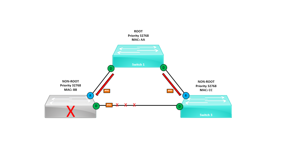
How can we protect against this?
We can use Loop Guard to protect the blocked port from transitioning into a forwarding state should the port stop receiving BPDU’s from its neighbour switch.
Loop Guard says, if I stop receiving BPDU’s on my blocked port – this means something is wrong therefore I will keep it blocked by placing the port into an “Loop Inconsistent” mode. Once the issue is resolved I will transition the port back to blocking state automatically.
Cisco recommends for the configuration to be applied on an interfaces by interfaces basis. Also a point to note would be that you cannot enable both loop guard and root guard at the same time.
Configuration Example
In the example below we will emulate a malfunction with a switch using “BPDU filter” and see how the blocked port behaves as it stops receiving BPDUs. We will then configure Loop Guard on an interface basis and again observe the behaviour to ensure it places the blocked into an “Loop Consistence” state.
The topology has been setup using GNS 3
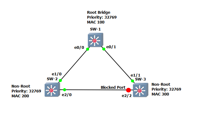
Step 1: lets have a look at the spanning-tree topology and verify the state of each switch.
SW-1
#show spanning-tree
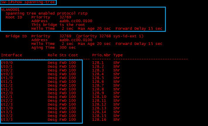
We can see that “SW-1” is running RSTP and it is the “Root-Bridge” with the lowest “Bridge-ID”. All ports on the “Root” are in a forwarding state.
SW-2
#show spanning-tree
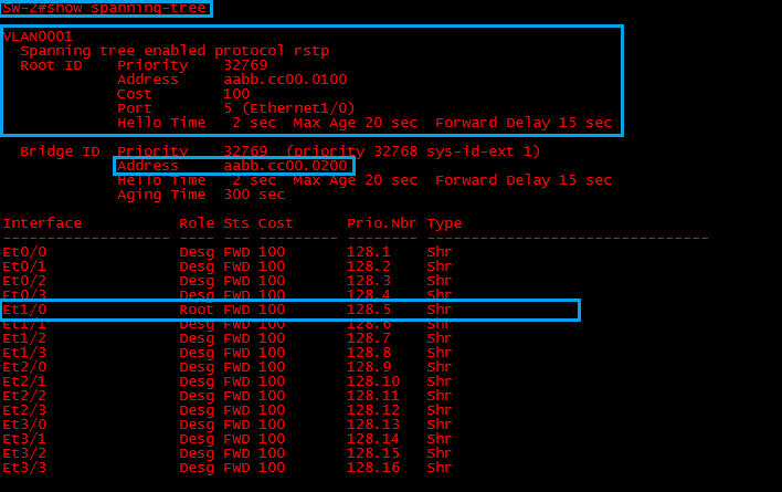
“SW-2” is running “RSTP” and it has identified “SW-1” as the “Root-Bridge” E1/0 is its “Root Port” with the best path to the “Root-Bridge”
SW-3
#show spanning-tree
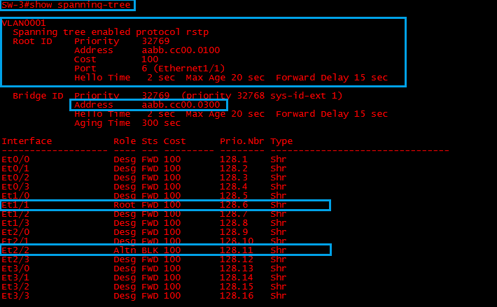
“SW-3” is also running “RSTP”, it has identified “SW-1” as the “Root-Bridge”, E1/1 has been elected as the “Root Port” and the redundant link on “E2/2” is being blocked.
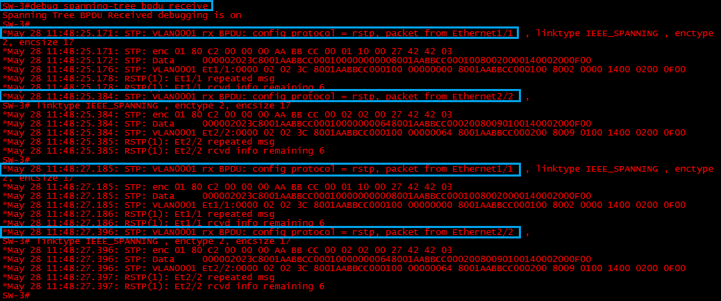
Step 2: on “SW-3” lets enable debugging to have a look at the BPDU’s that are coming in on the blocked port.
#debug spanning-tree bpdu receive
We can see that BPDU’s are being received from “SW-1” on “E1/1” and “SW-2” on “E2/2” every 2 seconds. These are being sent by the “Root-Bridge”
Step 3: Configure “BPDU Filter” on “SW-2” to emulate a malfunction with the device, as BPDU filter is enabled on interface “E2/0” the interface will not receive or send BPDU frames, essentially not participating in STP
#conf t
#Int e2/0
#spanning-tree bpdu filter enable

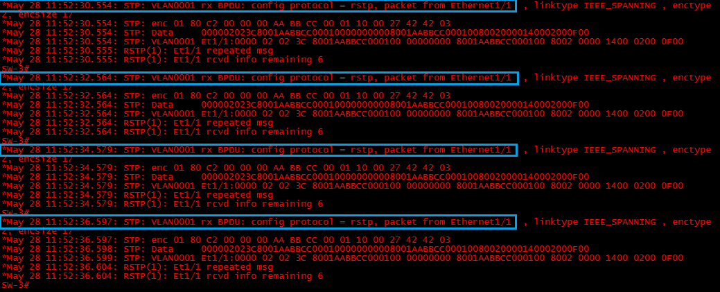
Step 4: lets verify on “SW-3” that it can no longer see BPDU’s on Interface “E2/2” by looking at the debug messages.
We can only see BPDU’s coming in from “SW-1” on int “E1/1” this is indicating that “SW-2” has a problem.
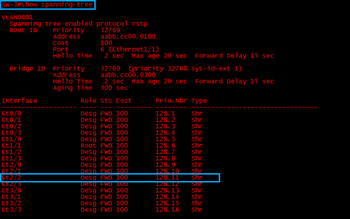
Step 5: On “SW-3” Lets take a look at the state of interface “E2/2” which was previously blocking.
#show spanning-tree
As suspected interface “E2/2” should now be forwarding, STP assumes that there is no longer a switch plugged into this port so it transitions it to a forwarding state. This has now caused a loop.
Step 6: Remove the BPDU filter configuration from interface “E2/0” on “SW-2” so that the port is blocked by spanning-tree again
#no spanning-tree bpdufilter enable
![]()
Step 7: lets configure “Loop Guard” on “SW-3” and protect against the failure
#conf t
#int e2/2
#spanning-tree guard loop

Step 8: re-enable BPDU Filter on interface “E2/0” on “SW-2” to replicate a switch malfunction once again.
#spanning-tree bpdufilter enable

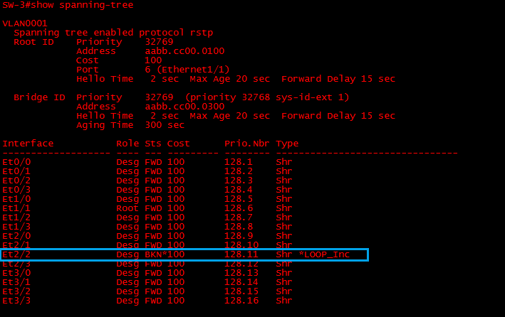
On “SW-3” we can see that interface “E2/2” has realised its not receiving any BPDU’s on a port that was previously blocked by STP therefore it has placed the port into a loop in-consistence state to prevent a loop.
![]()
If we take a look at the spanning-tree topology, we can see the port has been placed into a “Loop In-consistence” state
#show spanning-tree
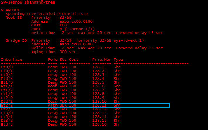
Step 9: lets now remove BPDU filter on int “2/0” on “SW-2” to emulate the issue has been resolved with the malfunctioned switch
#no spanning-tree bpdufilter enable
![]()
We can see on “SW-3” that Loop Guard has started receiving BPDU’s on int “E2/2” and has now restored the port back to a STP blocking state.
![]()
Global configuration
To configure Loop Guard globally enter the following:
#conf t
#spanning-tree loopguard default

